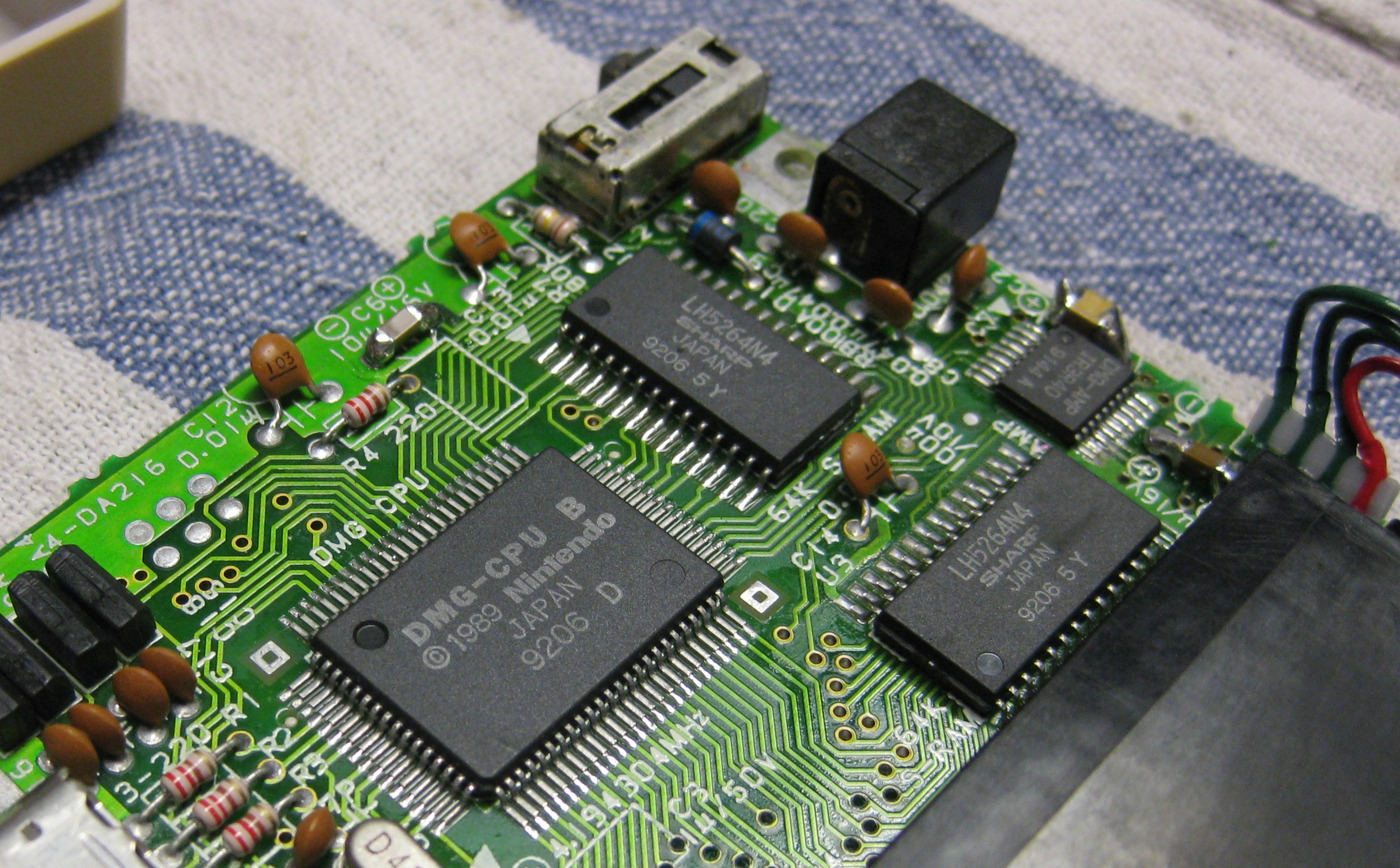
Its time to do a recap of the good old classic DMG 01
two pcbs with some elkos. I repaced all elkos to keramic caps.
2x 100u/ 6,3V
2x 100u /10V
1x 33u / 25V
2x 10u / 16V
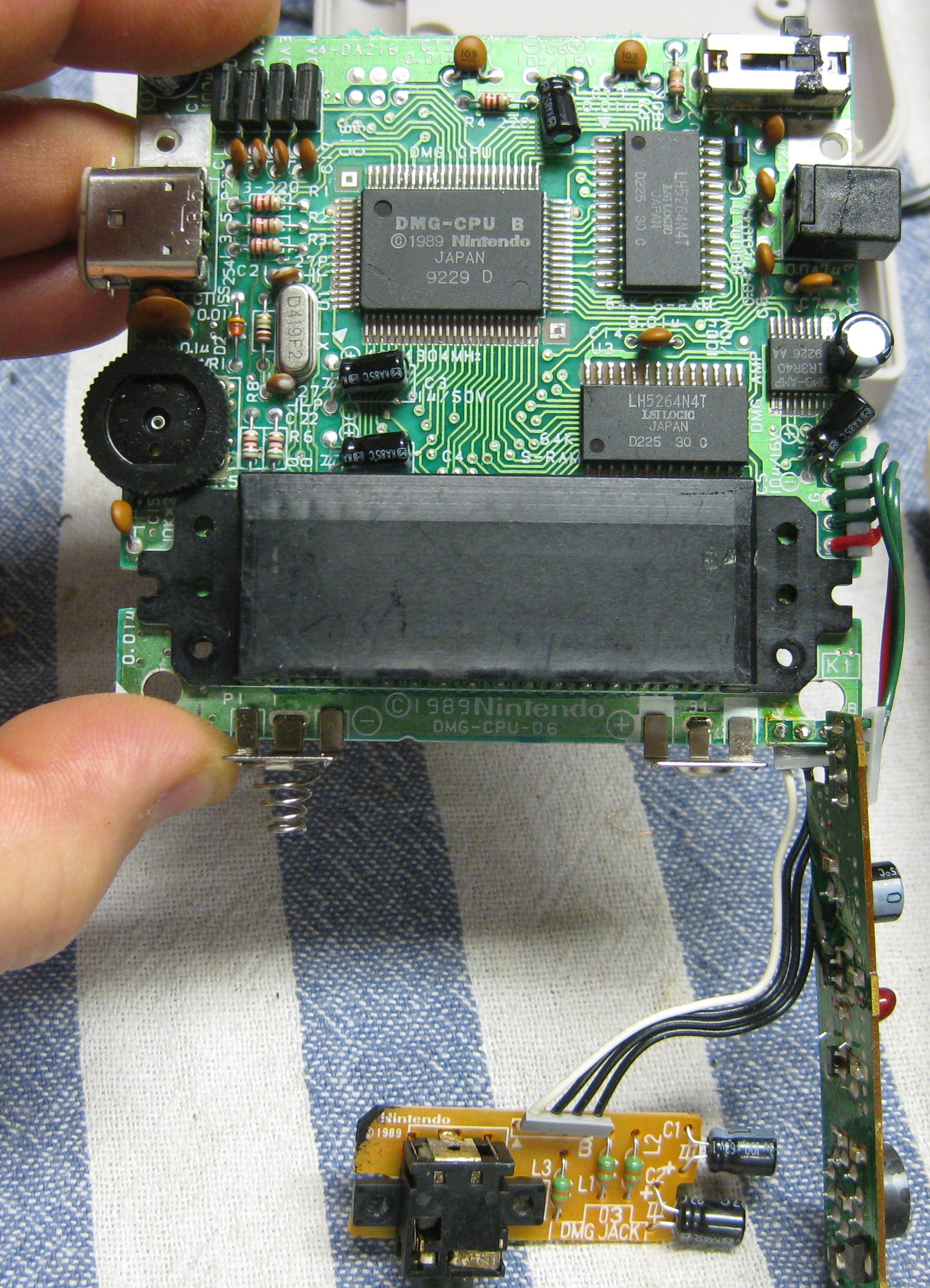
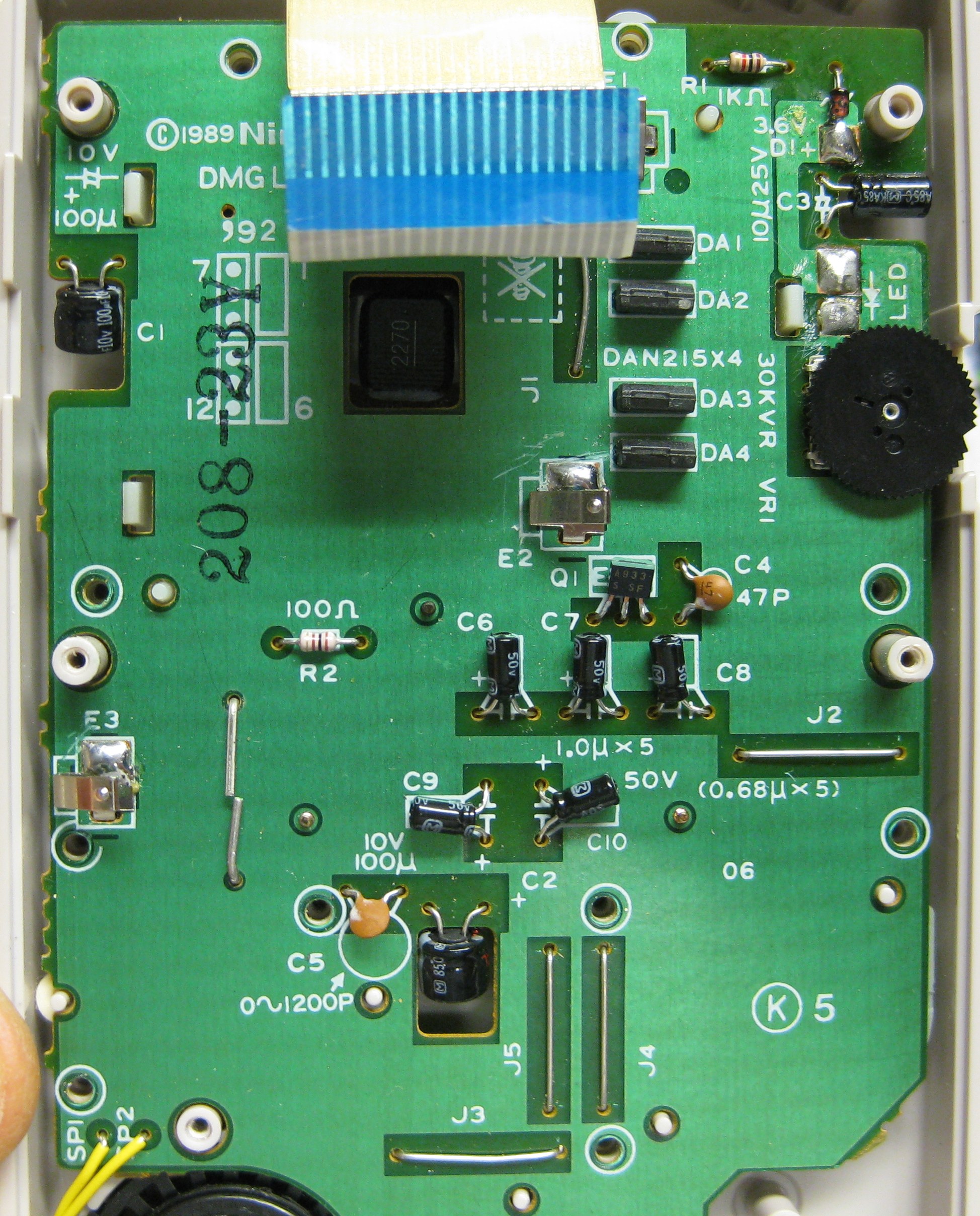
display/gamepad pcb
2x 100u /16V
5x 1u / 50V
1x 10u / 25V
here we go
Its time to do a recap of the good old classic DMG 01
two pcbs with some elkos. I repaced all elkos to keramic caps.
2x 100u/ 6,3V
2x 100u /10V
1x 33u / 25V
2x 10u / 16V
display/gamepad pcb
2x 100u /16V
5x 1u / 50V
1x 10u / 25V
here we go
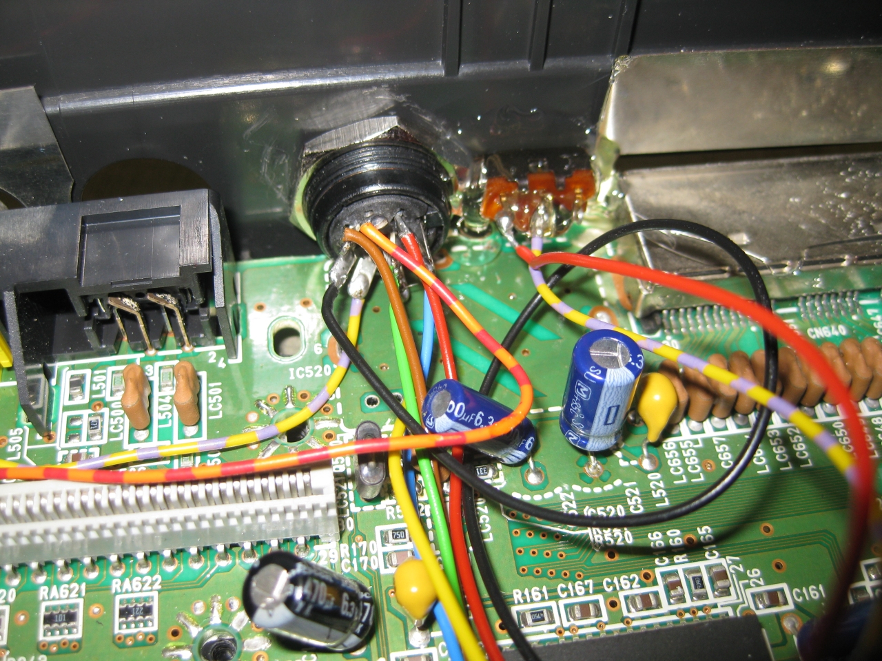
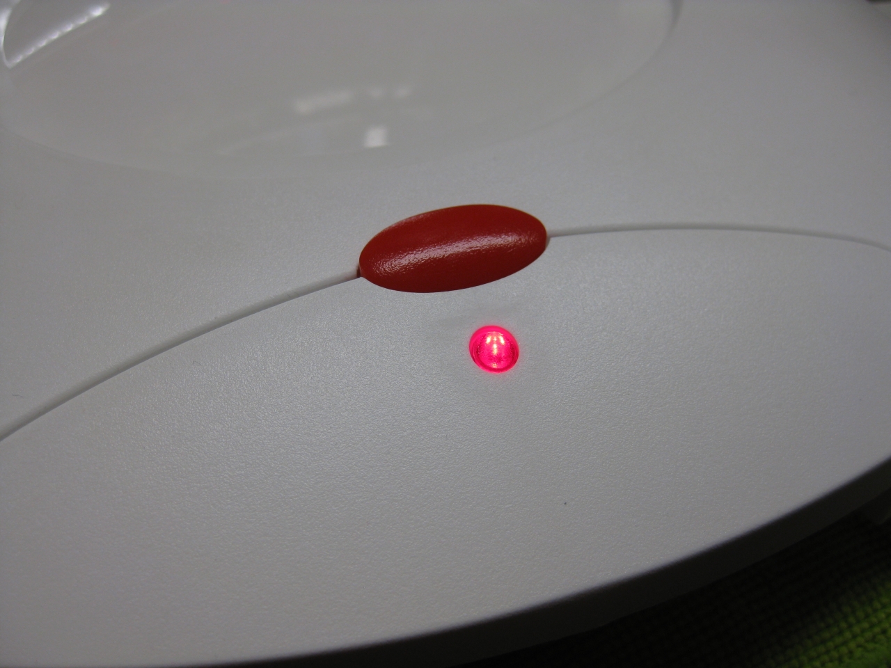
3DO Consoles outputing 240i Signal but with adding a switch you can set it to 240p
It only works on 3DO consoles with the VDP536 Chip
Pin 52 progressive output (high 5V)
Pin 52 interlace output (low GND)
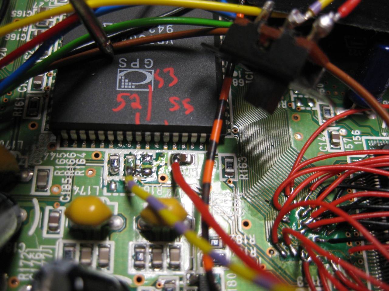
(red is 5V and yellow/purple leads to Pin 52)
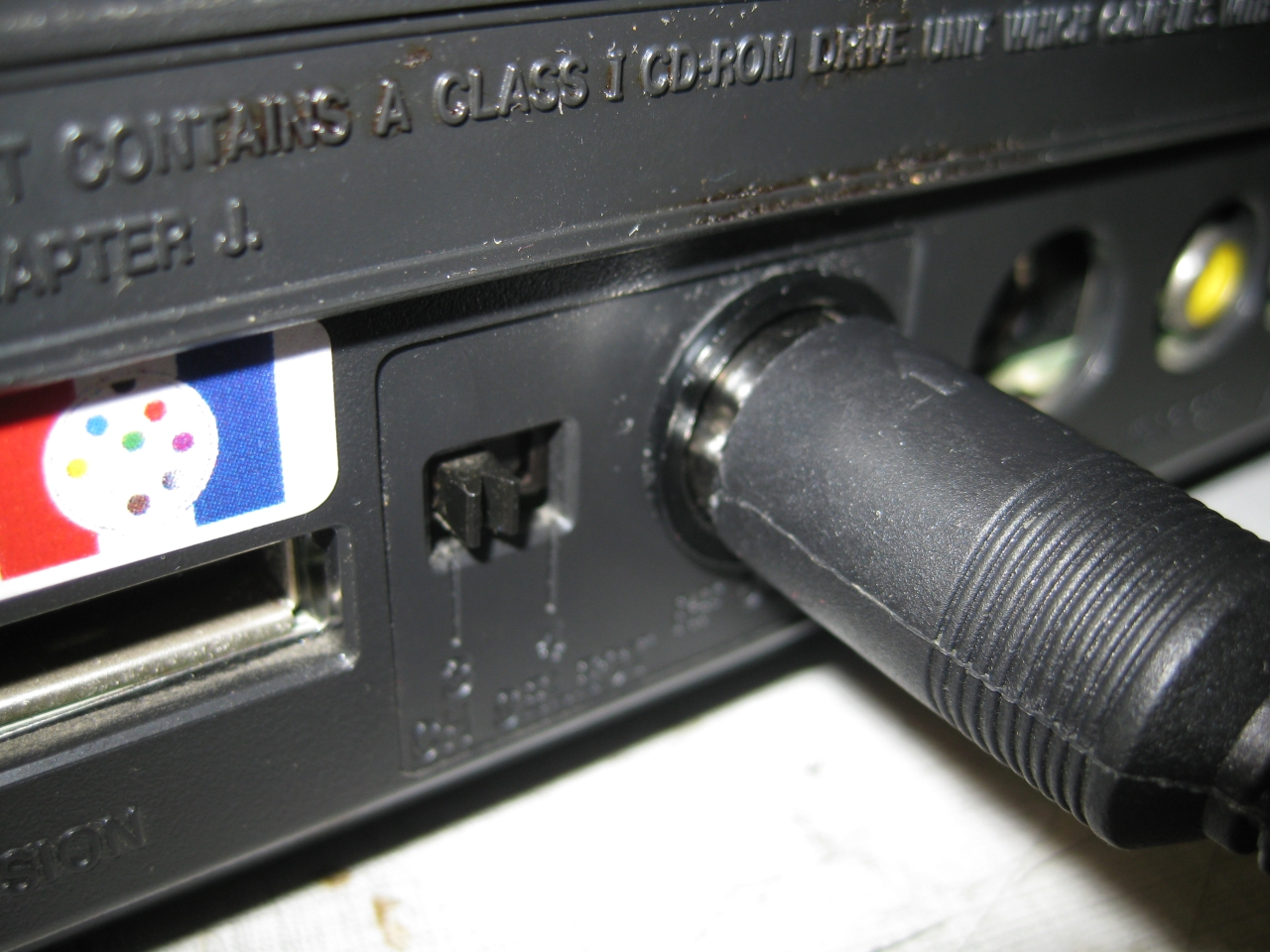
I removed the RF-Unit and put the switch at the same position of the chanel switching
For usage power up in interlace mod (switch off) and after power on the console
switch on to activate the 240p Mode.
If you turn the console on with 240p activated (switch on) you only get a black picture.
Same when you change a disc and you close the console with 240p activated (switch on)
the case need some cleaning
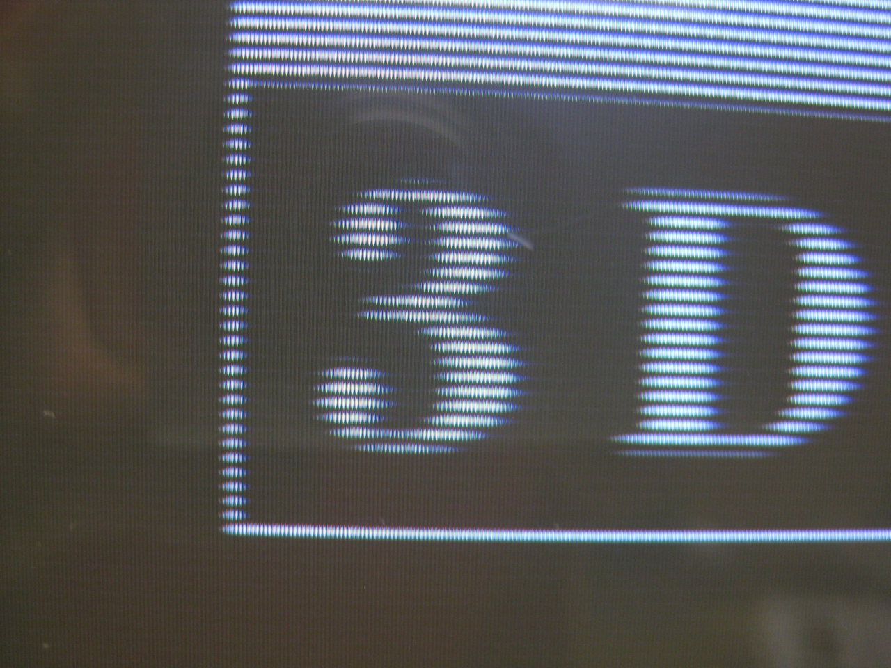
Some pics
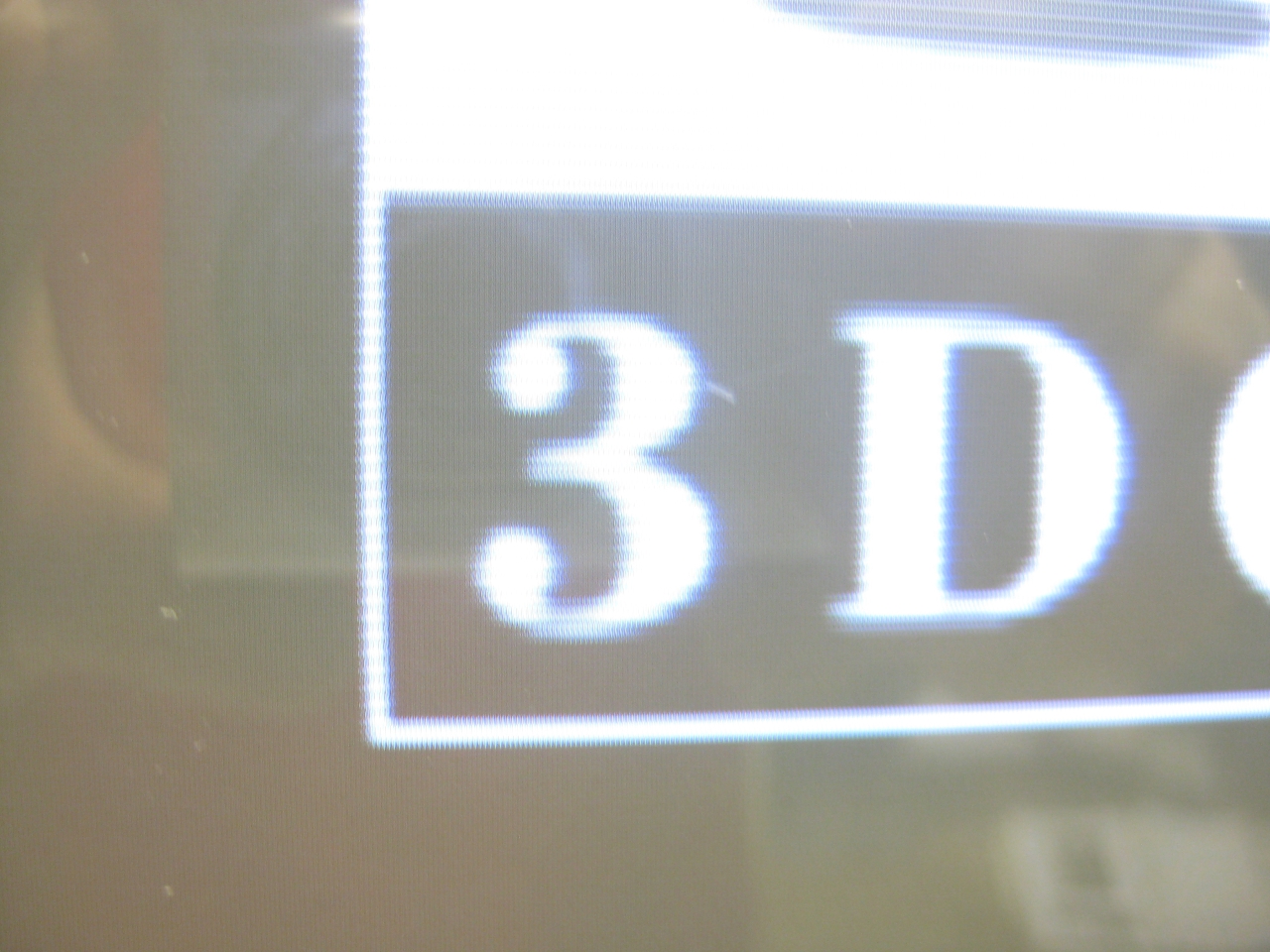
(interlaced)
progressive is sharper and more stable and not shaking anymore :-)))
Last wekk I got a great gadget called goDMD Clock. The main usage of it is to show the time, date, temp and Pinball Animations from the DMD.
This new version is build with 2 RGB-Led Array in a total resolution of 128×32 Pixel.
You can order it here (If you have trouble with the shop mail me at info@wolfsoft.de)
Here you can see what I am talking about
After contact with the developer, he added image rgb support to the editor 🙂
https://bintray.com/sker65/pin2dmd/Editor#files
Here you will find a package including one demofile. gridlee You only have to change variable base to your path were the package extracted
To do some animations for goDMD you have to use mame. I am using groovymame, because it can be set to output native pixel resolution of the games. So you will get a pixelperfect output for the goDMD.
start mame via commandline: groovymame -mngwrite griddle.mng griddle and do some gaming. After exit you will find a griddle.mng.
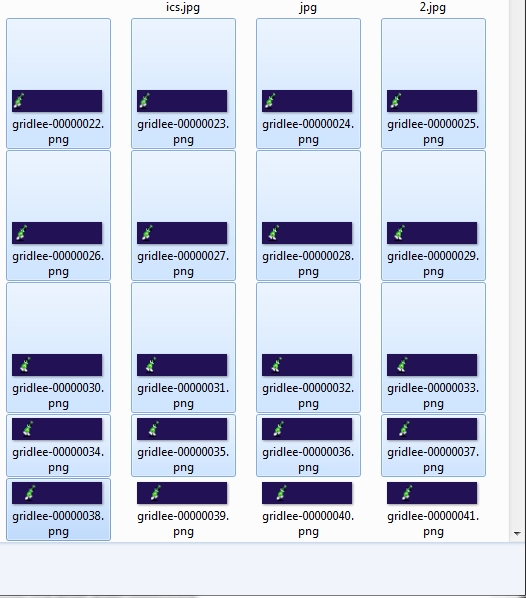
To split the griddle.mng into pictures I used a programm advmng
start it in the path where the griddle.mng via commandline: advmng.exe -x griddle.mng
After this you will get a lot of pictures like: gridlee-00000022.png (Resolution: 245×240)
With the help of irfanview (a pictureviewer) you can create a custom selection (under edit) with Width: 128 and Height: 32.
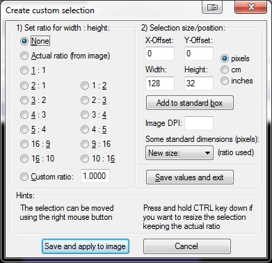
After Pressing the Button: Save and apply to image you will see a window on top of the left png.
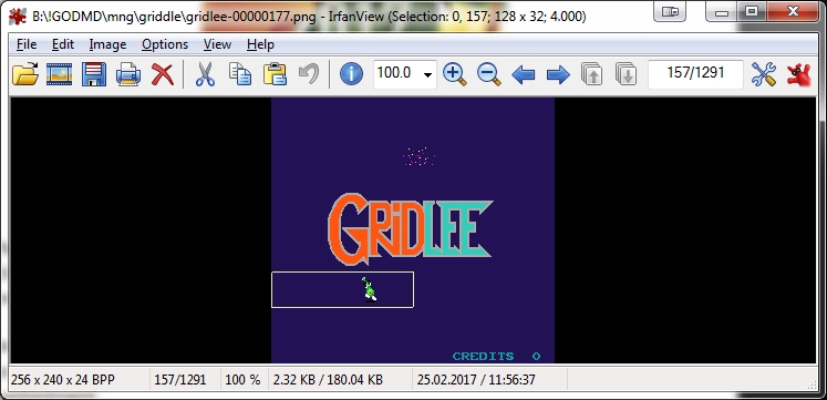
Move it with the help of arrowkeys to the area of interest
In Top Line you see (Selection: 0,0) this marks the X,Y Position. You have to enter these values in
Under File: Batch conversion (set to PNG Output Format) and press Advanced Button: Here you can set the X-pos, Y-pos Position
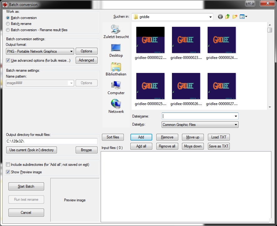
Mark the amount of png you want to crop and add them
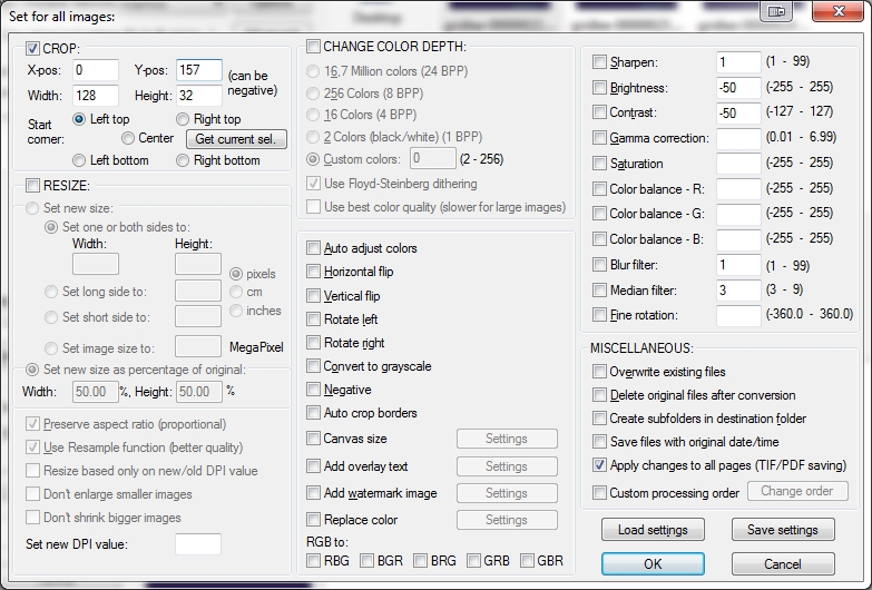
Start Batch
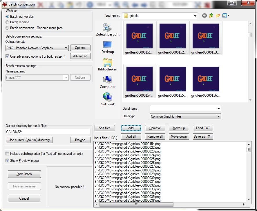
now you have a lot of cutted pictures in the right resolution
now put a animaions.properties in this folder
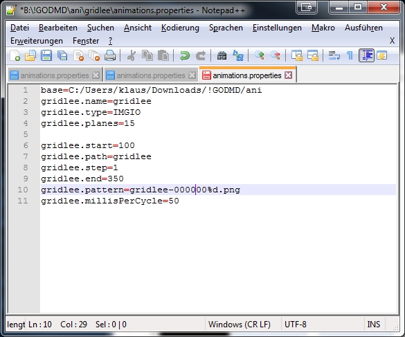
After this try to import it in the pin2dmd editor under animations: Load Animations
Here you can download new Fonts for the goDMD Clock ArcadeFonts_go_DMD
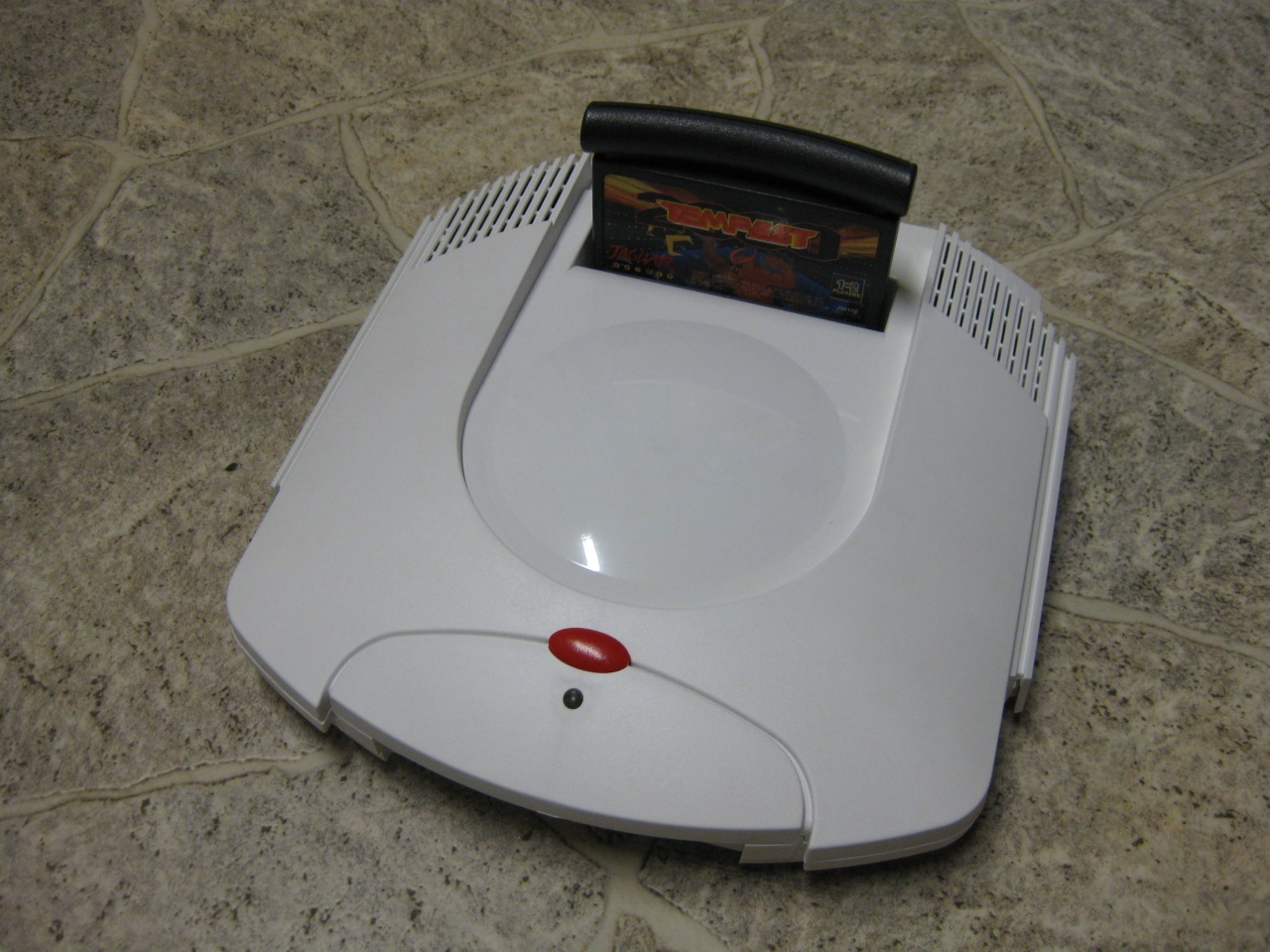
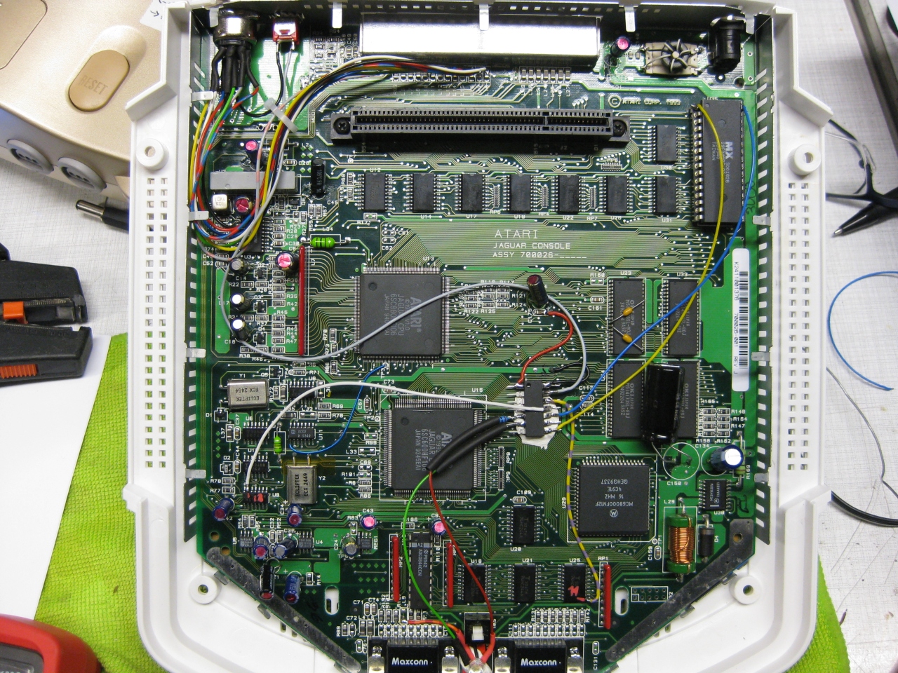
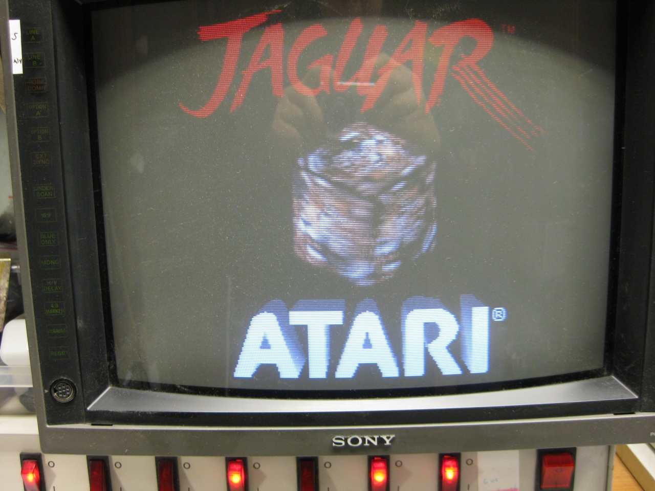
I got a white „dental“ case and its time to make the jaguar ready for 2017 😉
The title is something strange, but its comming from a Sega Saturn Mod years ago (the code is based on this). The Saturn reset button is used for change region and 50/60Hz.
You will need:
-pic16f630
-button
-RGB-Led
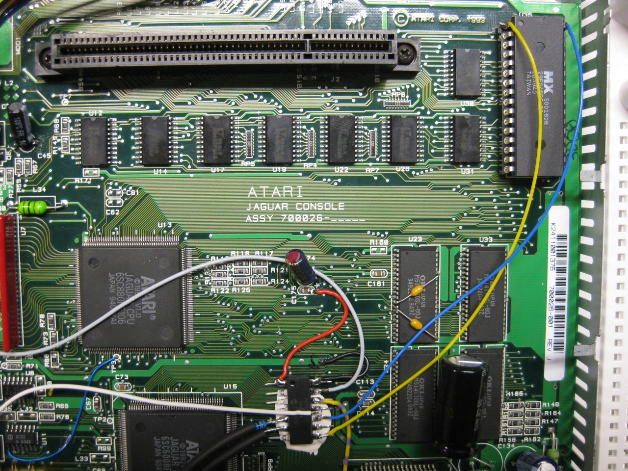
I removed the RF-Unit to put my „standard“ DIN Connector and for adding a button instead of the chanel selector. With the help of this tiny button you can select between 50/60Hz.
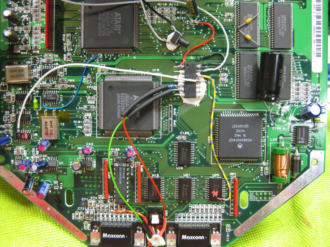
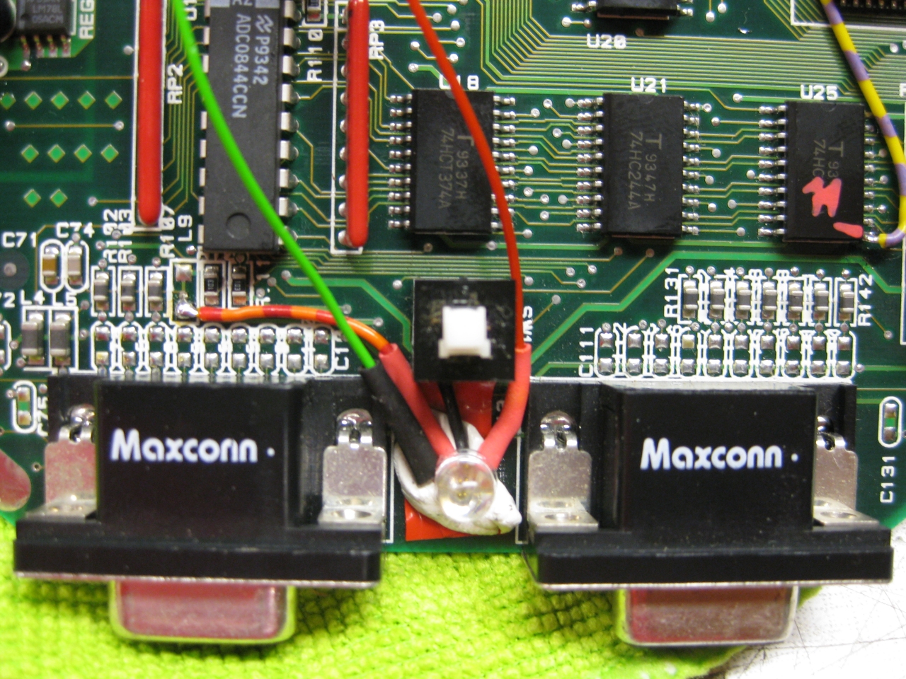
(Overview)
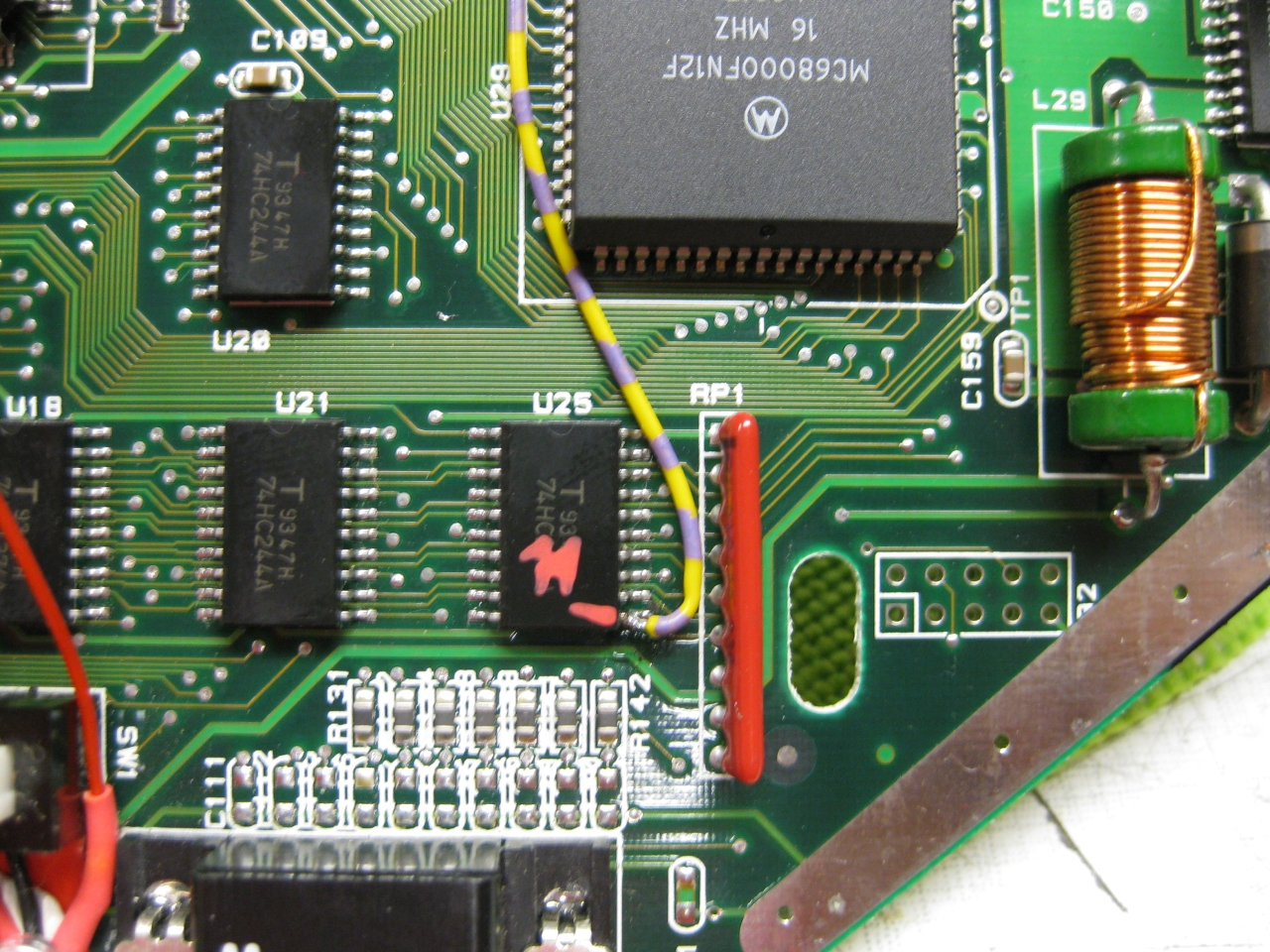
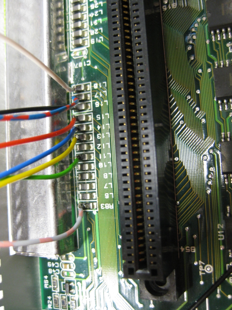
(U25 Pin 11 sets the Console between 50 Hz (GND) and 60Hz (5V)
I used a US 60Hz Jaguar for modding, so you have only to solder this wire to Pin 11
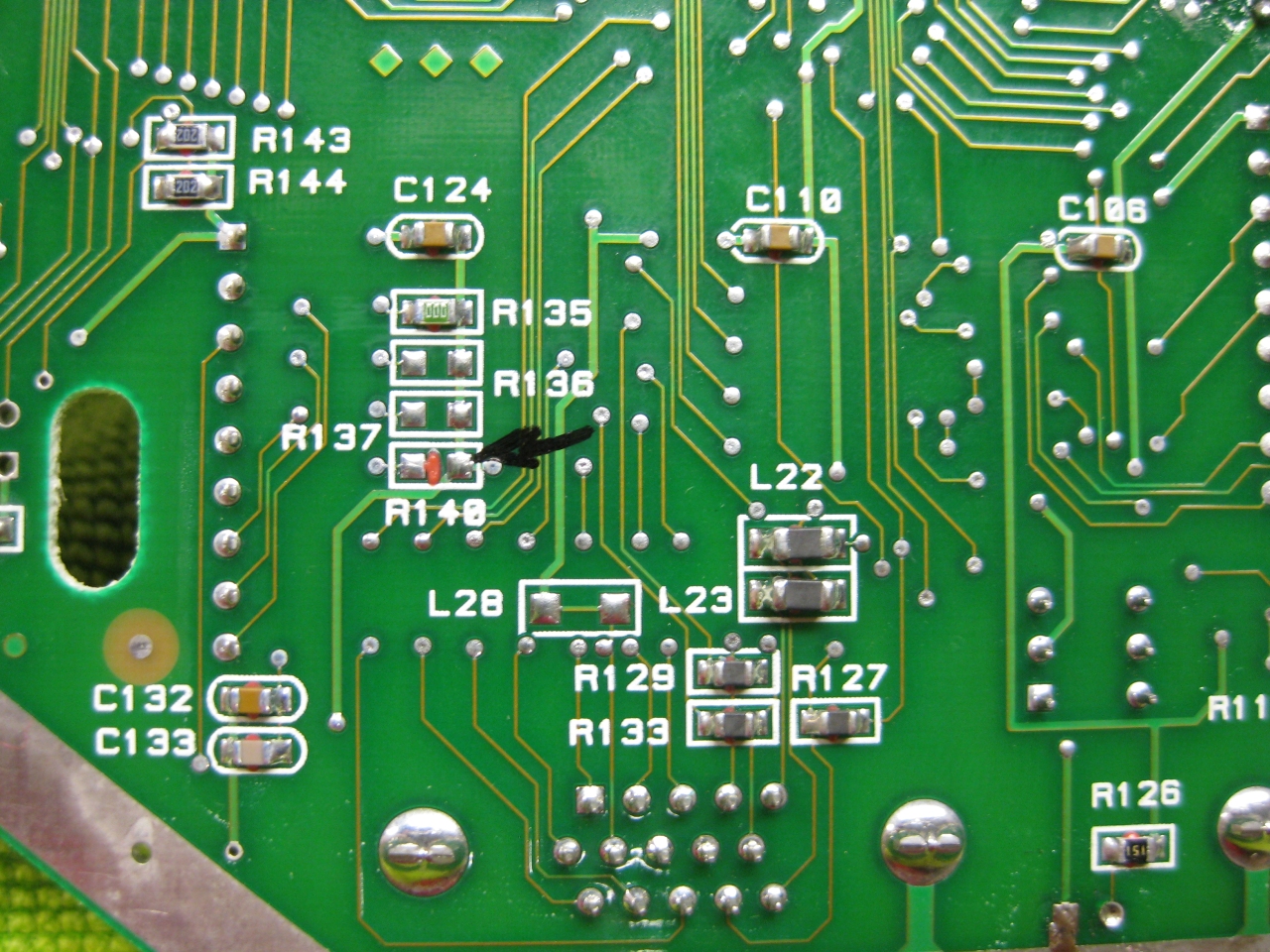
Attention If you use the PAL console you have to look downunder and remove a Resistor R140!
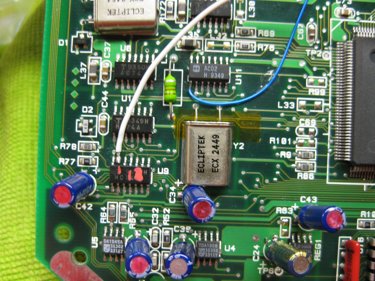
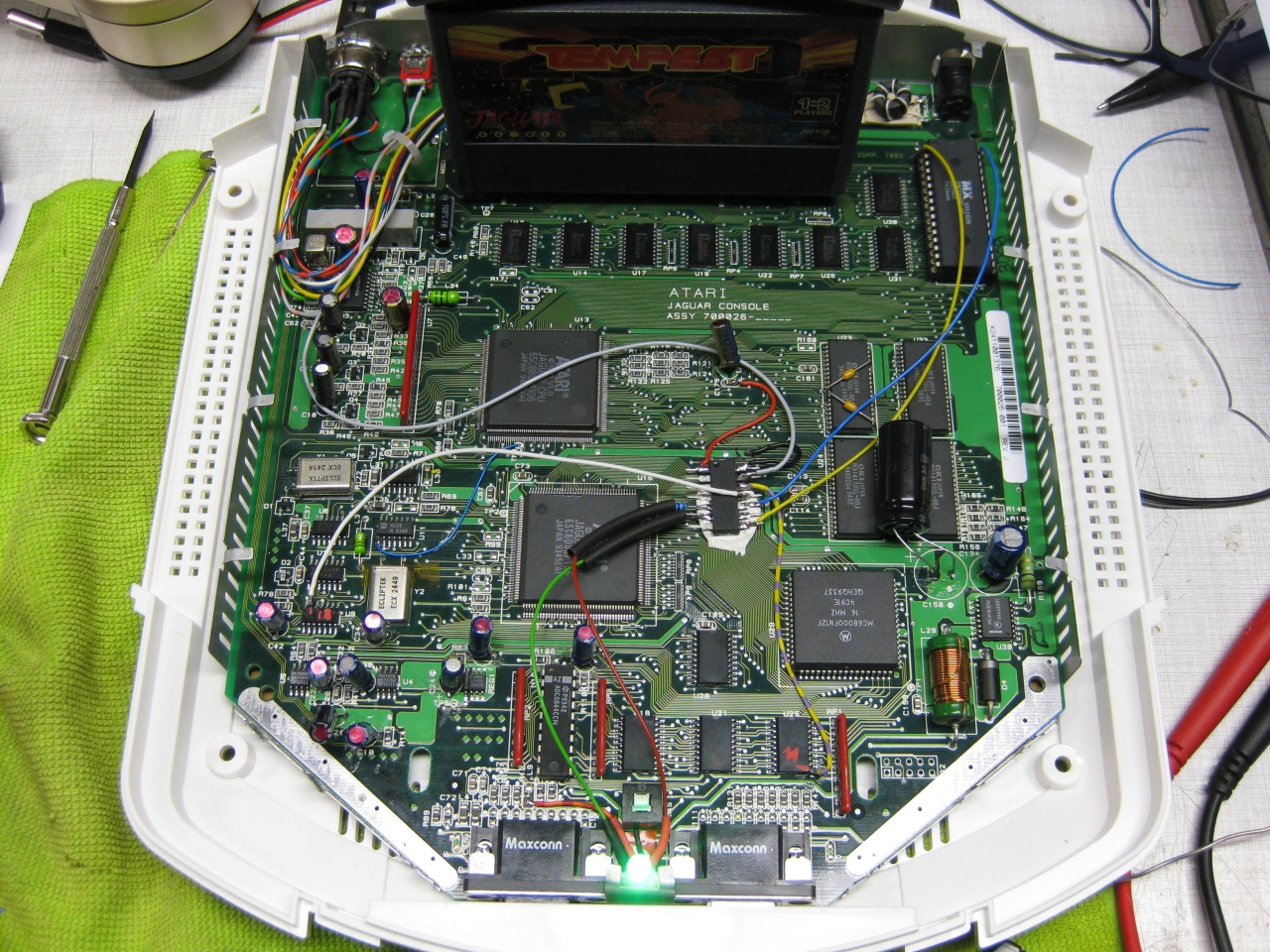
(The Reset Line you will find U9 Pin 13 (GND = reset)
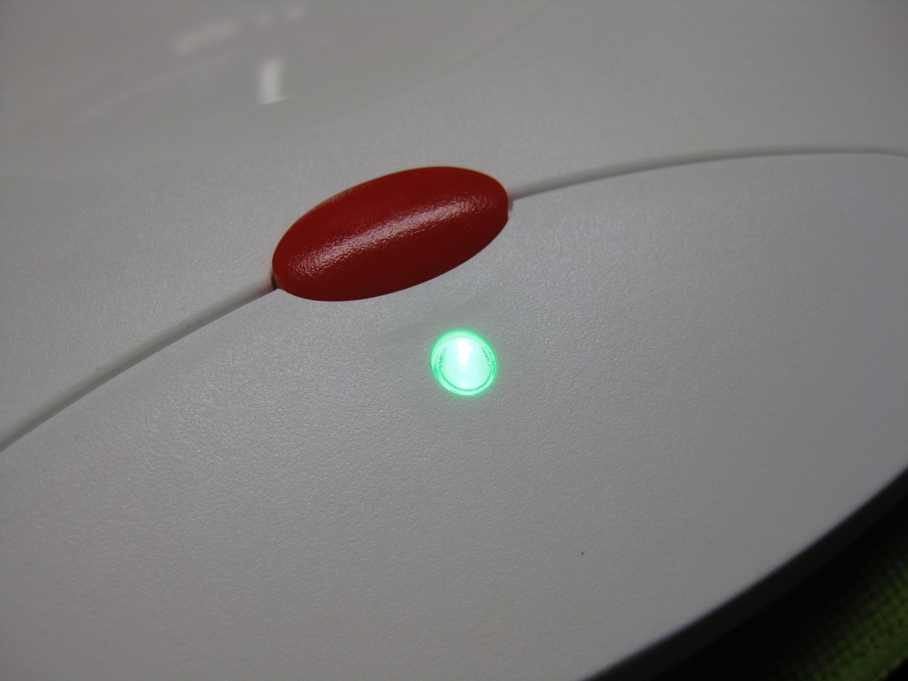
I removed the original LED and put instead a RGB-Led.
I set red for 60Hz and green for 50Hz.
If you find blue better, no problemo. But red/gn are the real colors of the Jaguar used in their countrys.
Usage:
Its like the switchless Mod for the Sega Saturn.
a) When you push the button for a moment. The Jaguar will do a reset
b) you push and hold the button. Now the Color of the LED will toogle between green and red. When you release the button
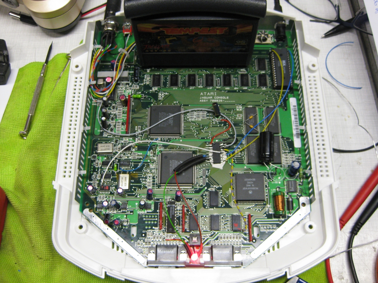
at red -> Jaguar Resets and starts with 60Hz
at green -> Jaguar Resets and starts with 50Hz
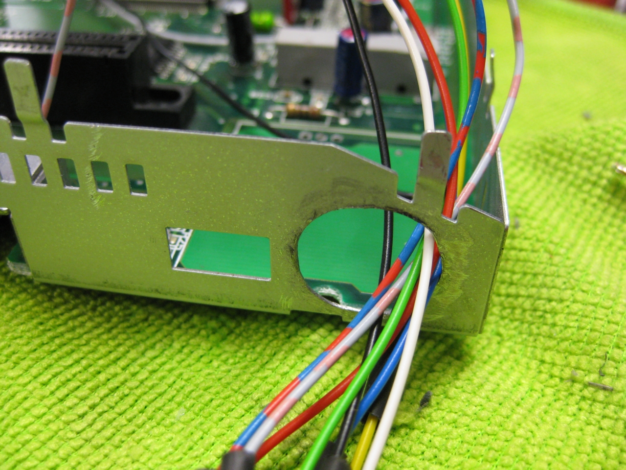
(bigger hole for Din RGB-Connector)
(RGB-Pinout)
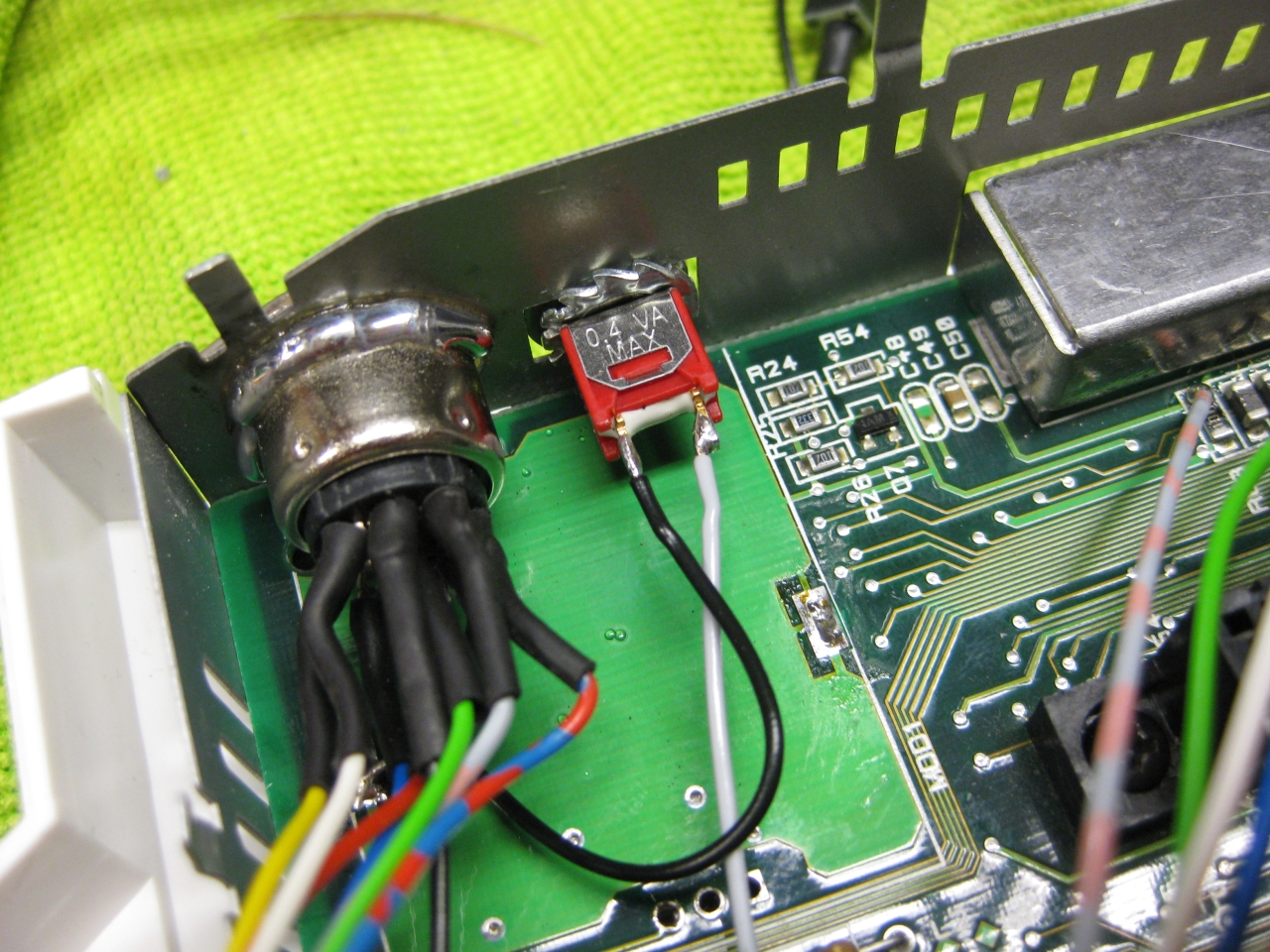
(Reset button)
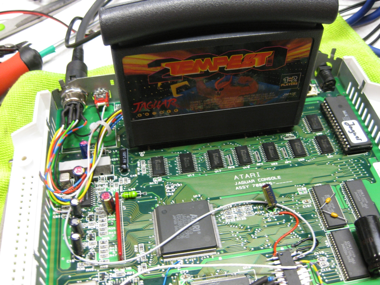
(overview)
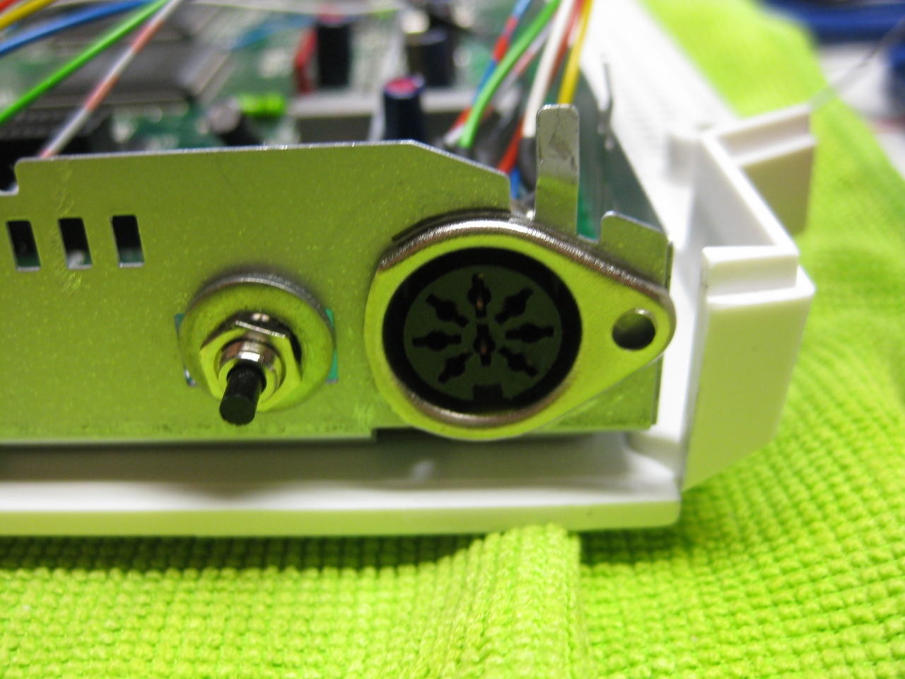
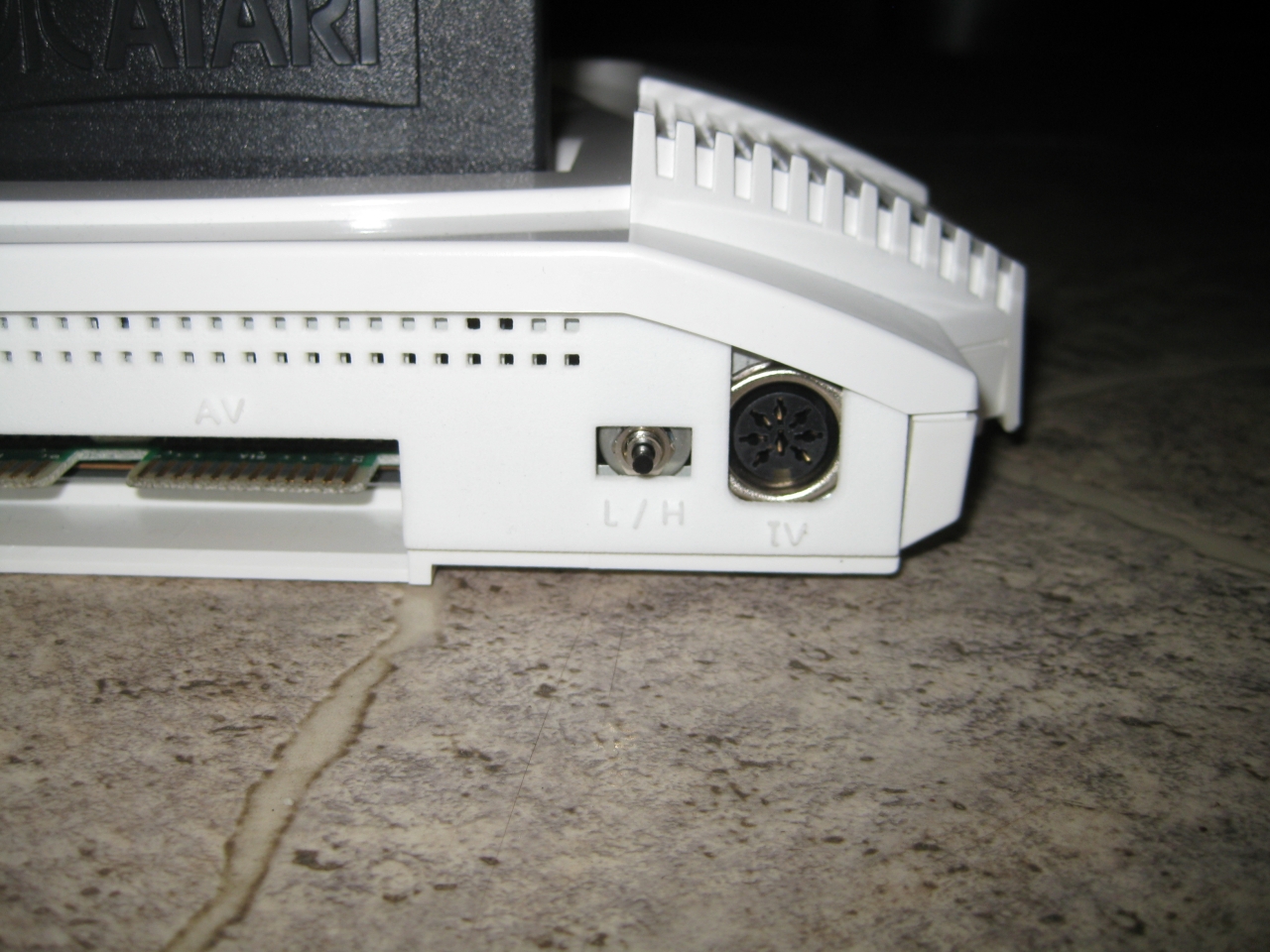
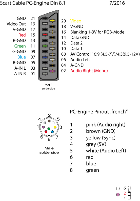
(my standard Din Pinout, based on modified 5 Pin Din PC-Engine + 3 more for RGB)
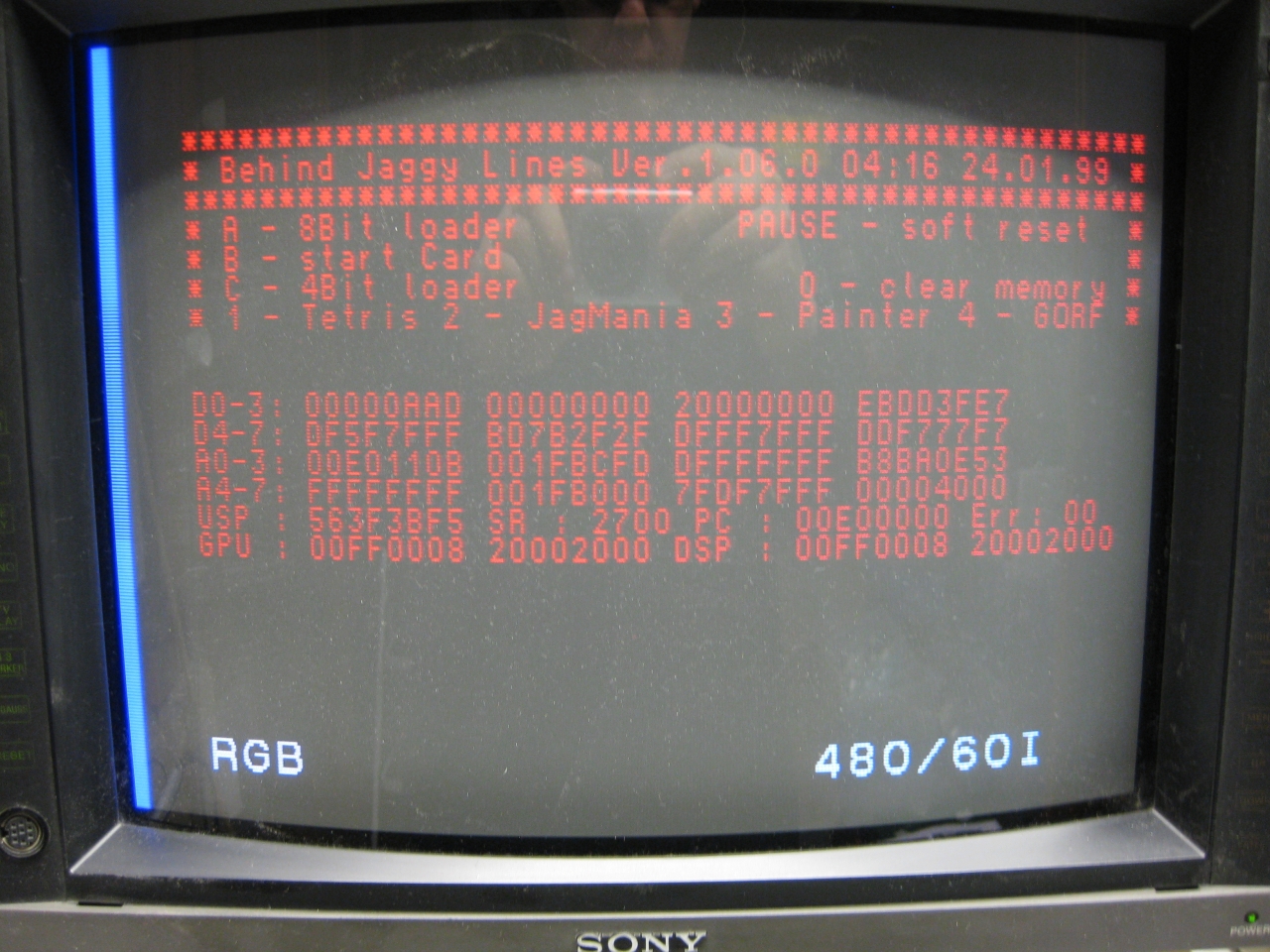
Its time to add a 2nd Bios to the Jaguar.
You have to remove the original Jaguar Bios and use a DIP 32 socket.
With the help of a 29f040 FlashRom I added jagbios and BJL1.06
You need to concat the bios files:
Use: windows command: copy /B jagbios.bin + jagbios.bin + jagbios.bin + BJL106.bin 4in1bios.bin
and burn 4in1bios.bin to the 29F040 FlashRom
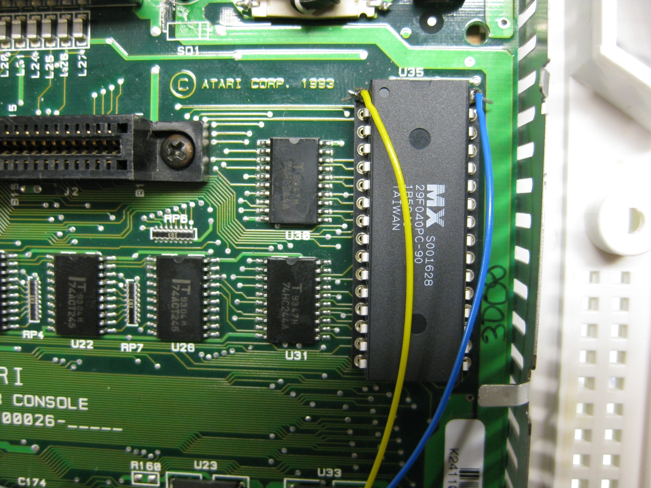
(overview)
Update 23.6.2017
I put a switch beneath the Power Switch to make it like a „real switchless“ mod.
So the Power switch can pressed a litte to:
OR
Press it more deep to Power Off and Power ON like normal
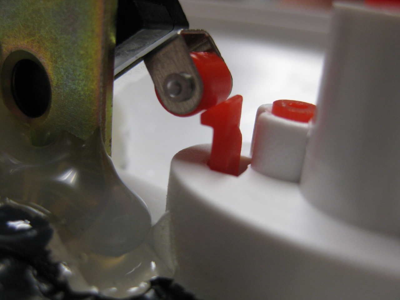
I used a little switch with a ball at the end and put it inside like this:
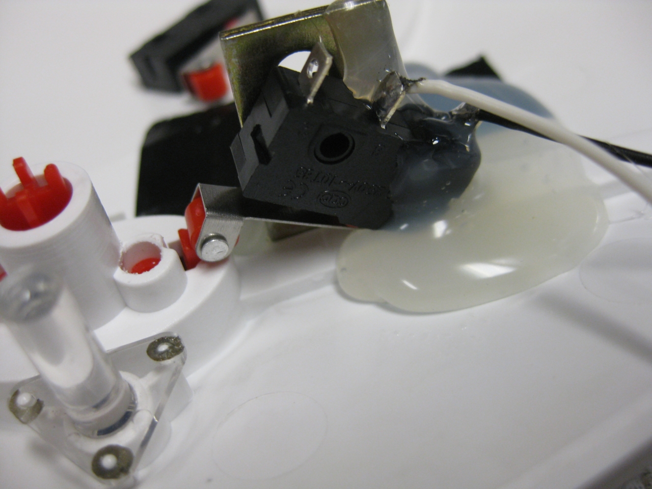
standard
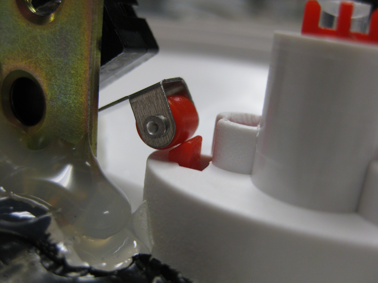
with button pressed a „little“
Youtube Video
(Sorry about wrong JBL speaking its BJL Loader 😉
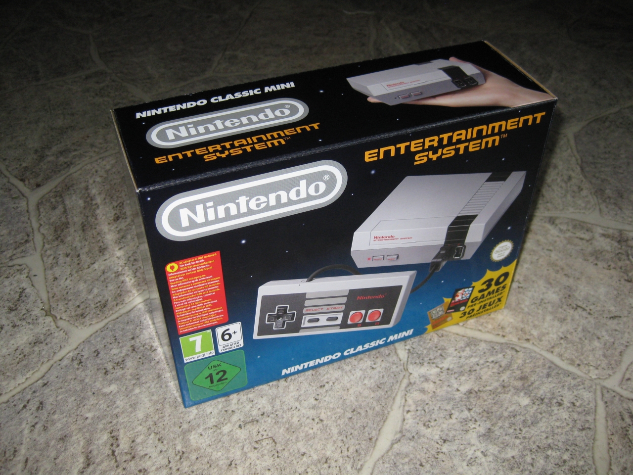
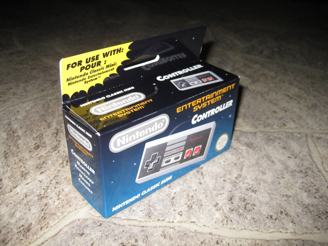
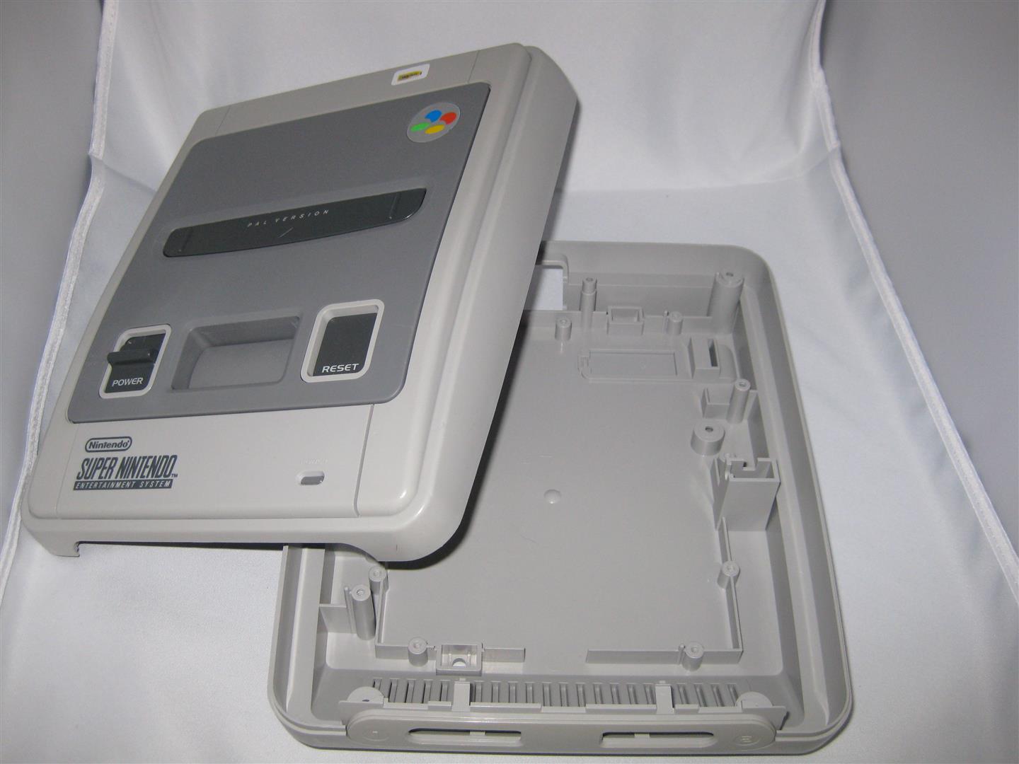
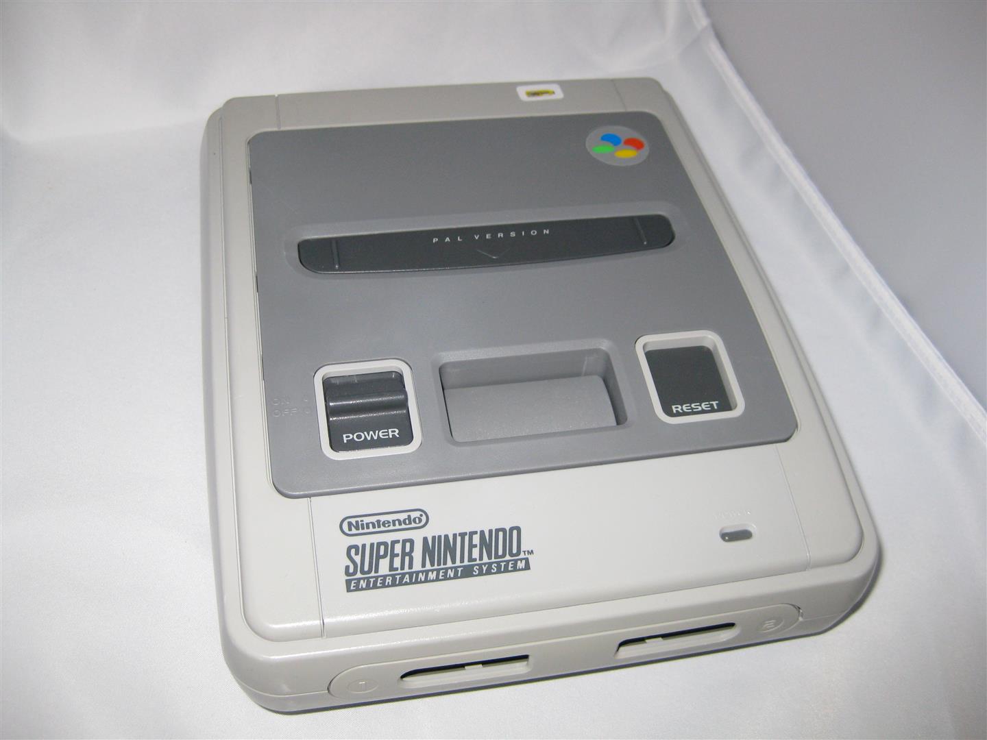
Today I got the NES Mini including a second Controller.
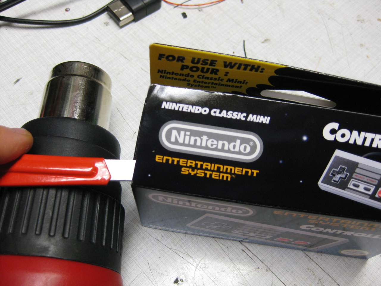
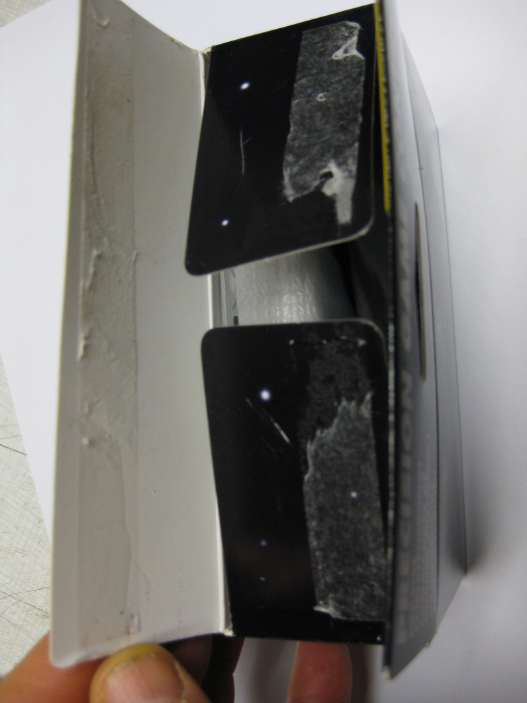
So what we have to do is to open it reversible ;-). With the help of a cutter knife and a heatgun. It opens good and here we are.
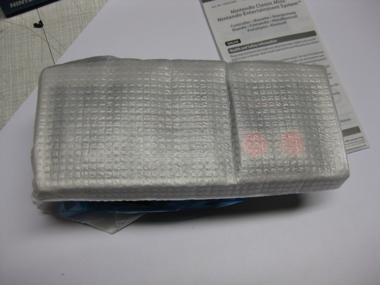
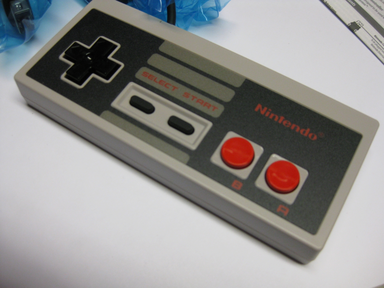
Hu after over 30 years a new NES Controller in my hands…
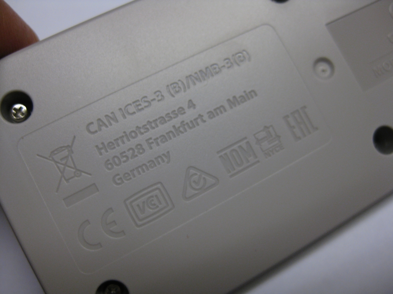
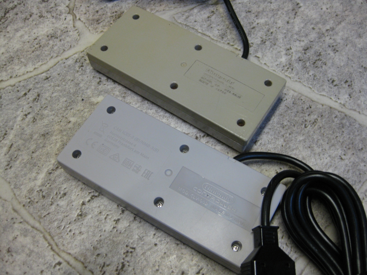
and look on the rear side. Graved the german adress of Nintendo
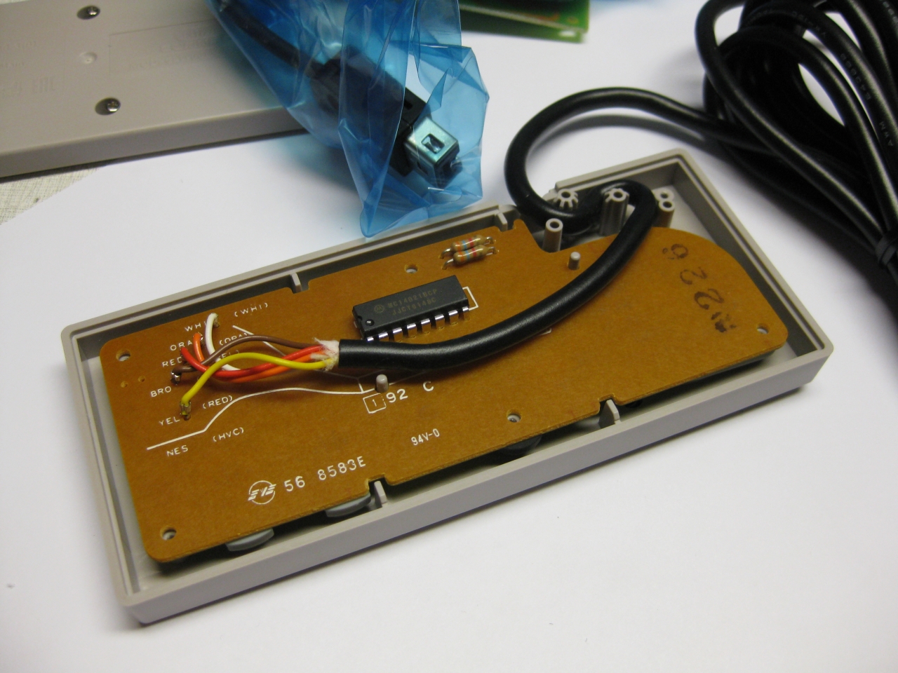
the wii/ NES Mini PCB
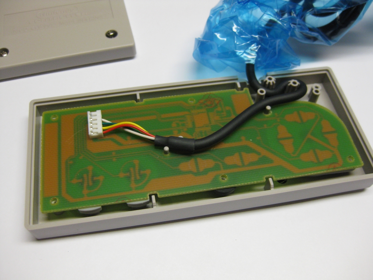
I took an old good shaped PCB from a „junk“ original NES Controller
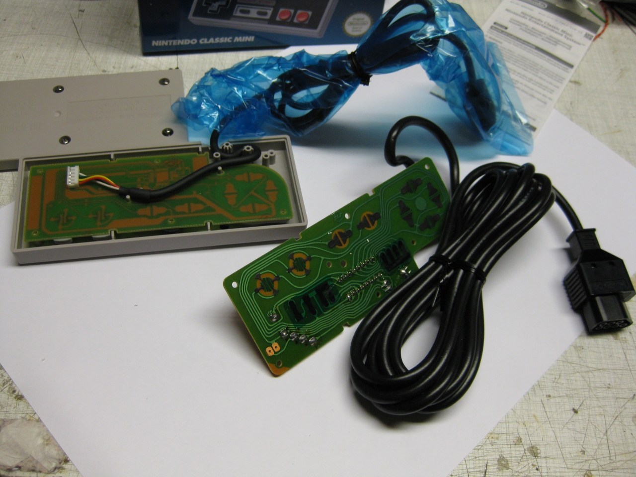
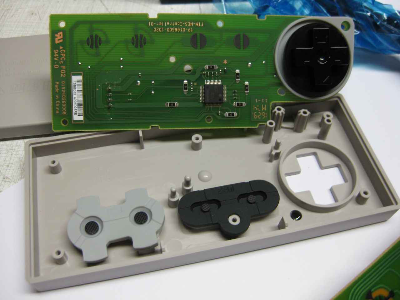
and it fitts like a charm
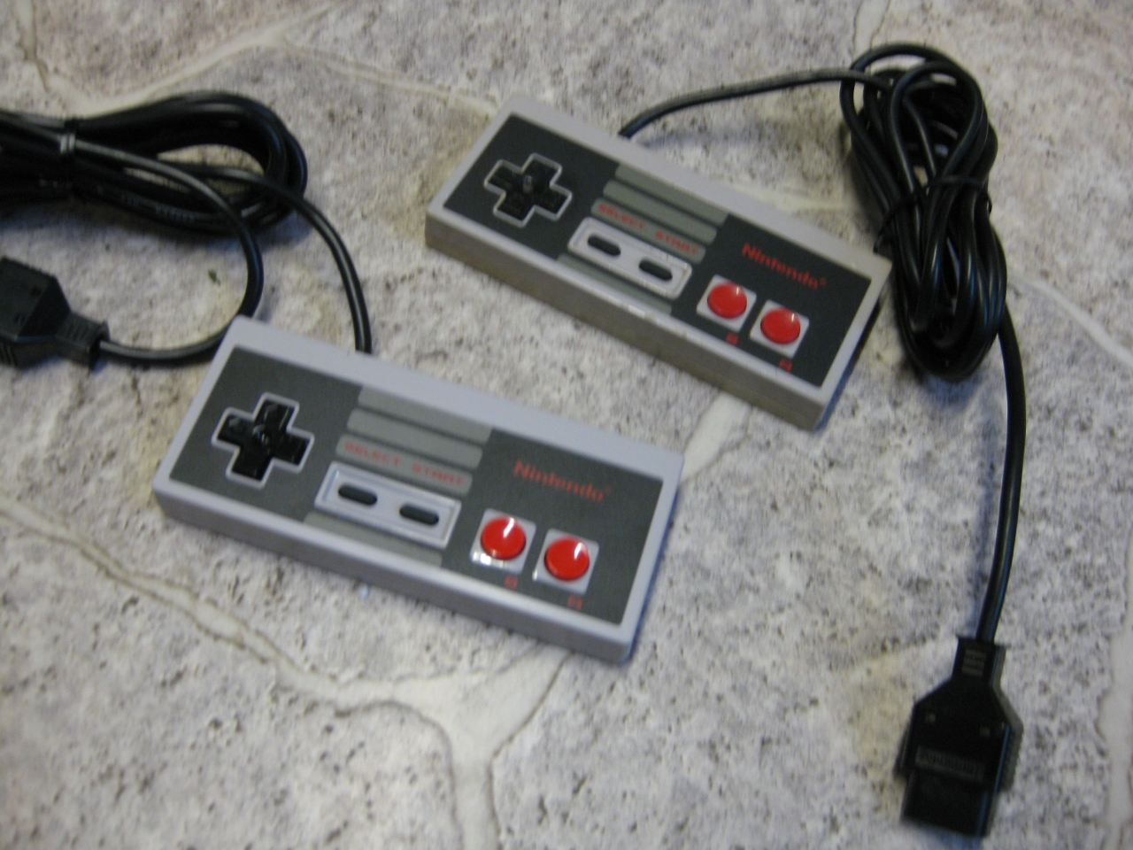
and it playes like the first day in 1986
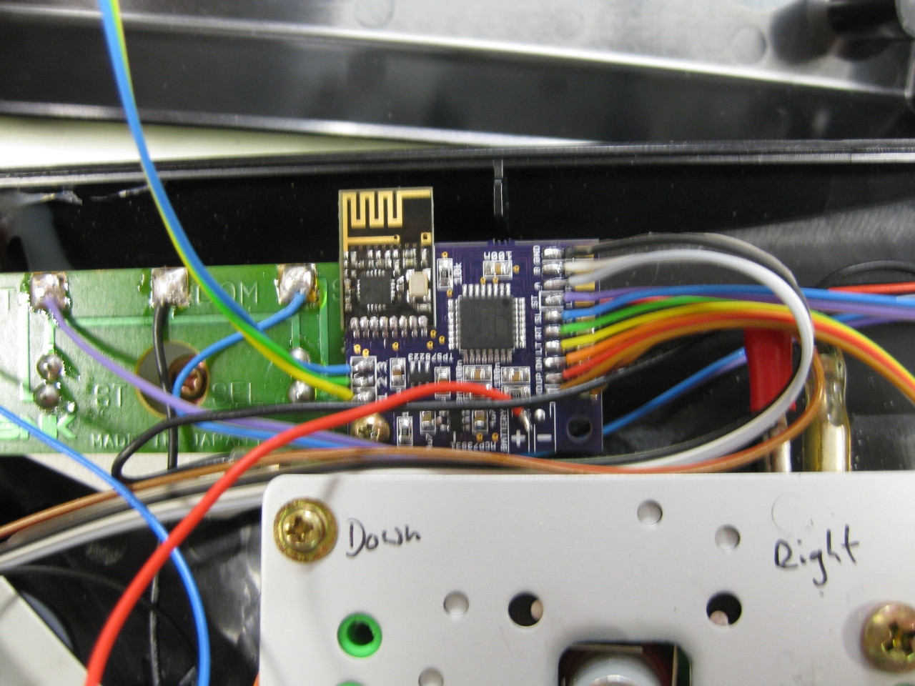
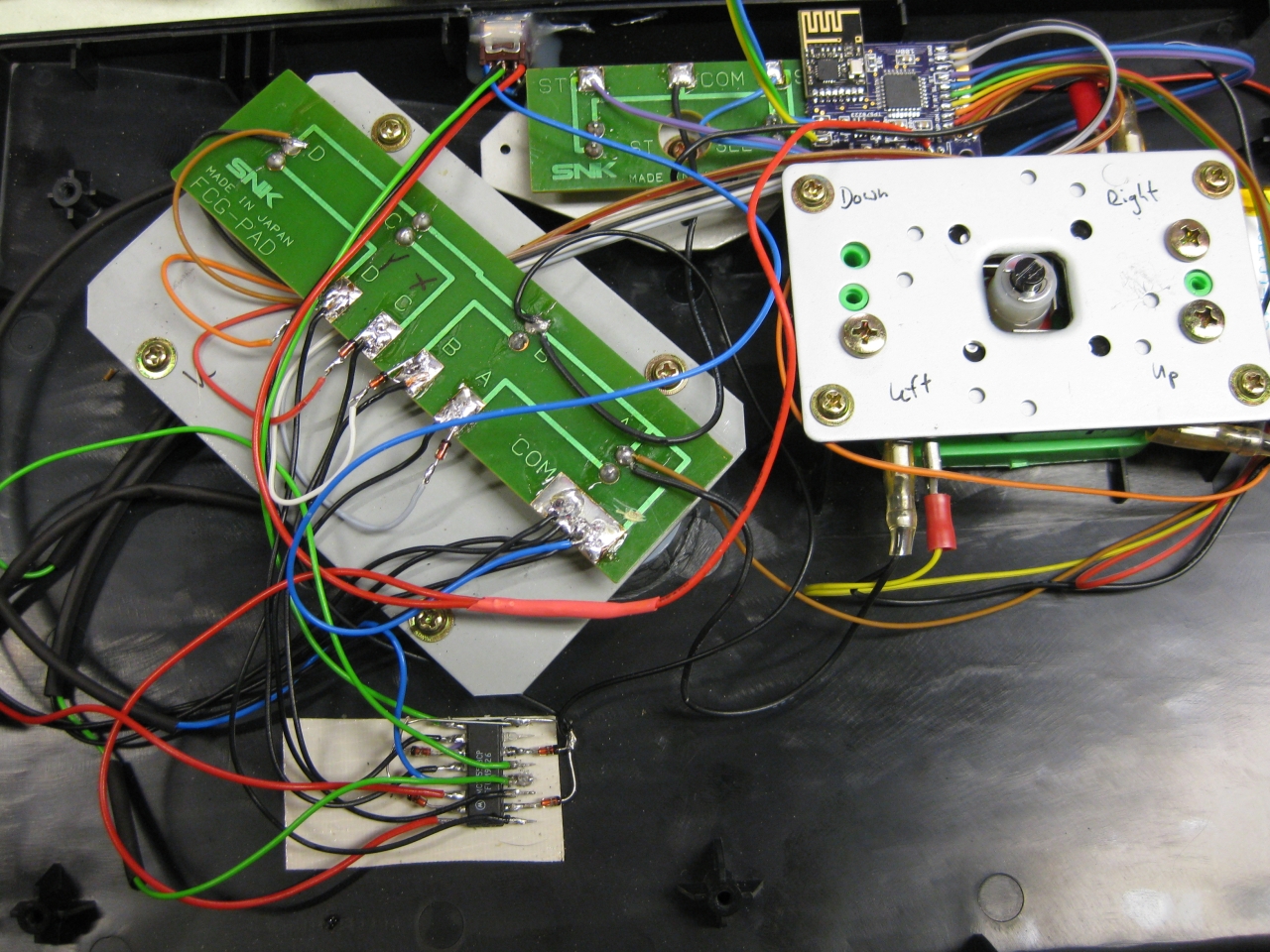
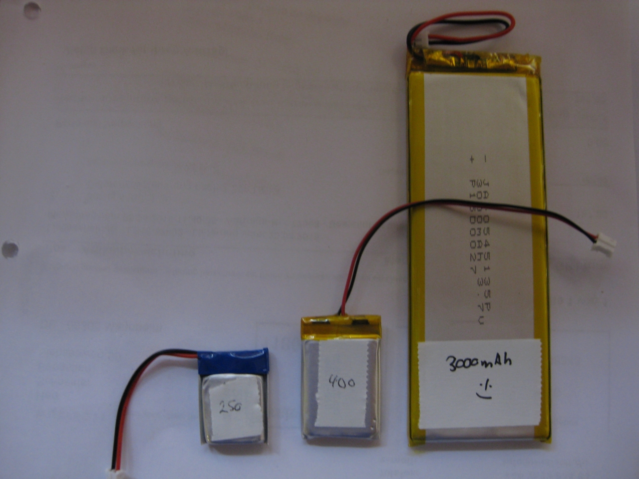
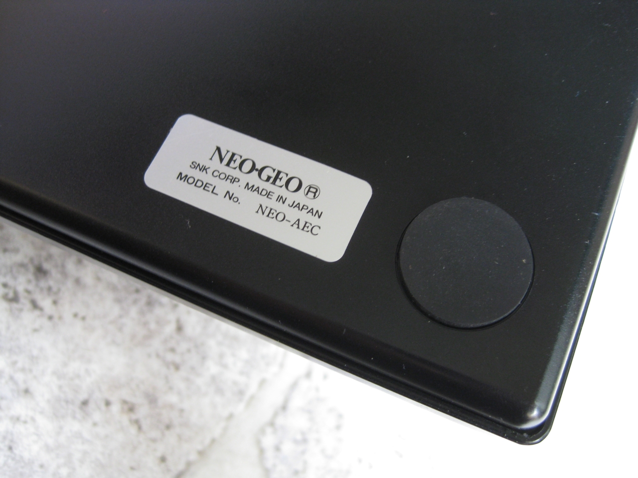
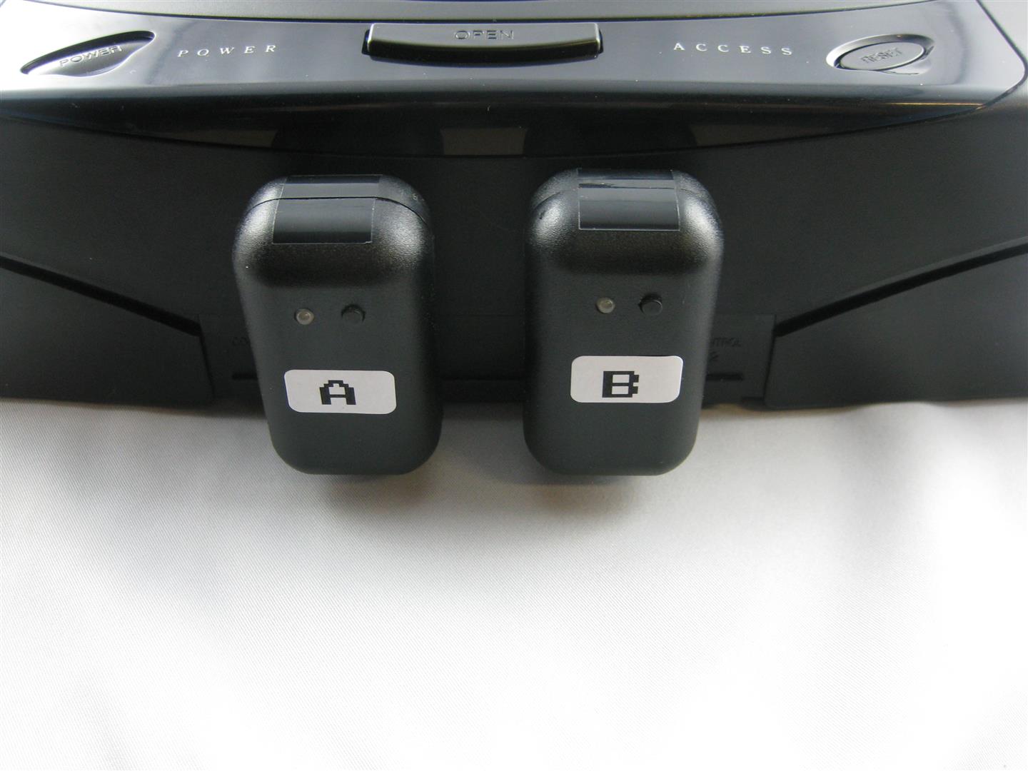
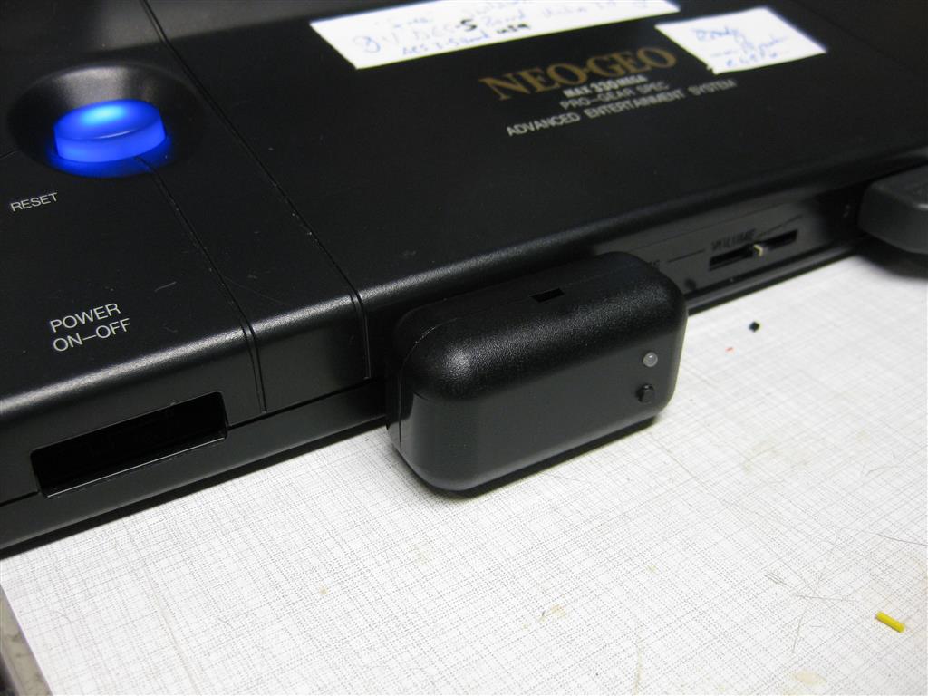
I sacrifice my NeoGeo Board to make it wireless with uwrc. thanks to micro again.
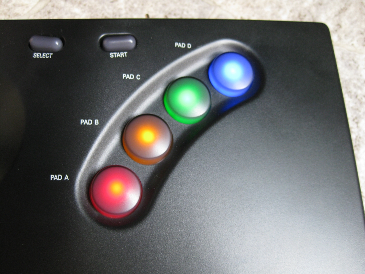
Here I used my Led modded NeoGeo Controller and put all together. Because of the Leds and more need of current. I used a bigger LiPo. The future will tell how long it works.
https://blog.smarterwolf.de/?p=664
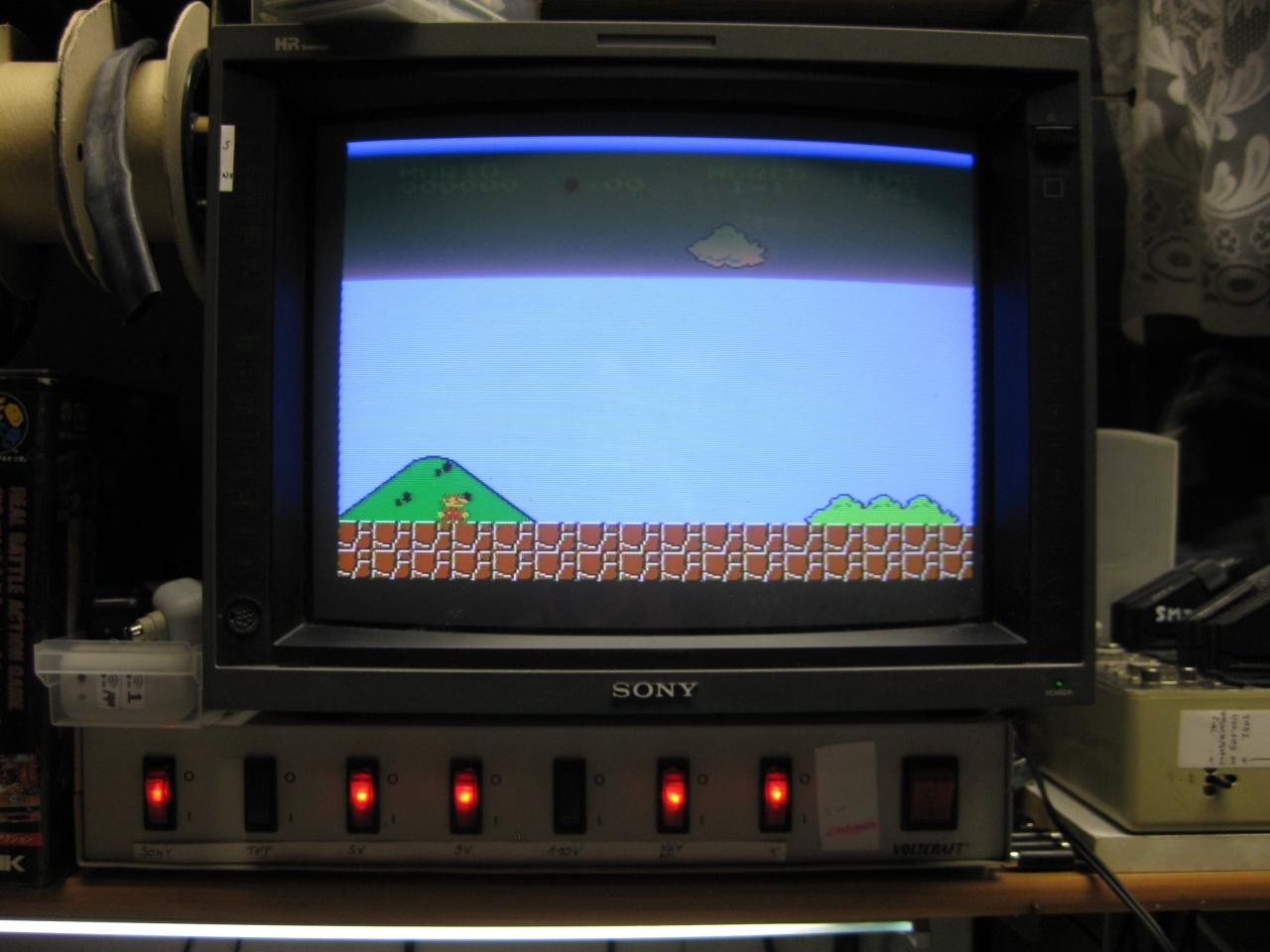
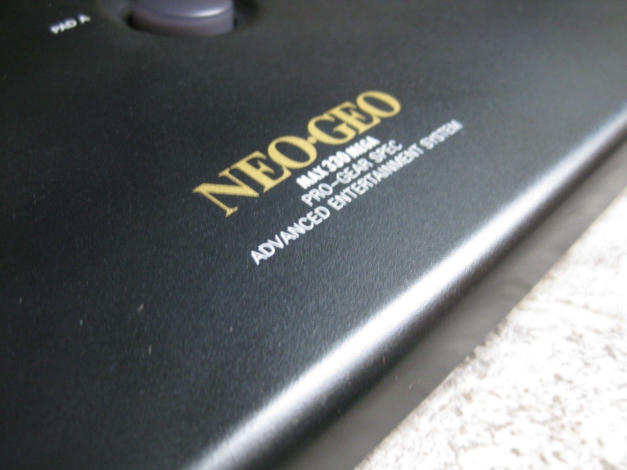
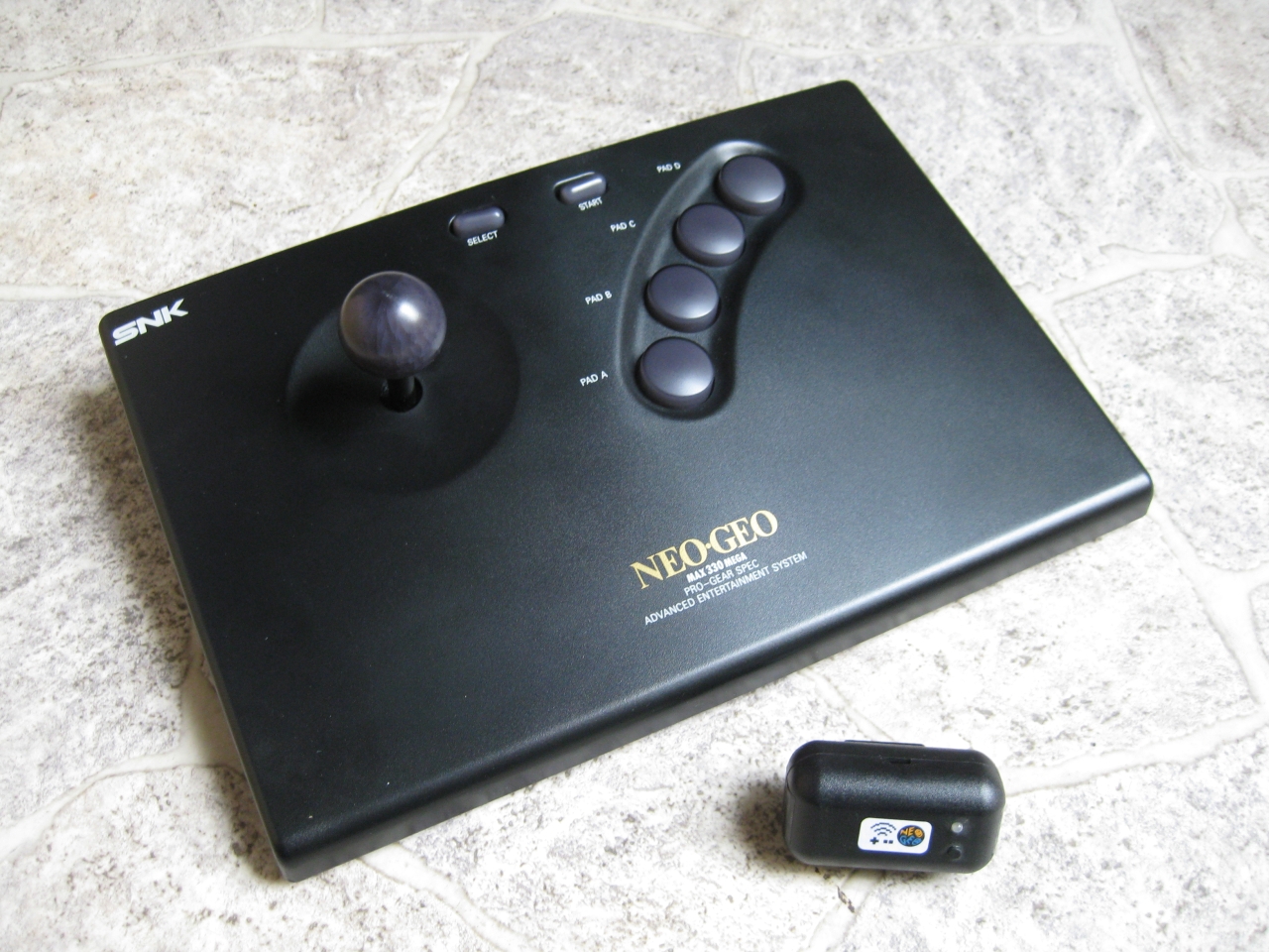
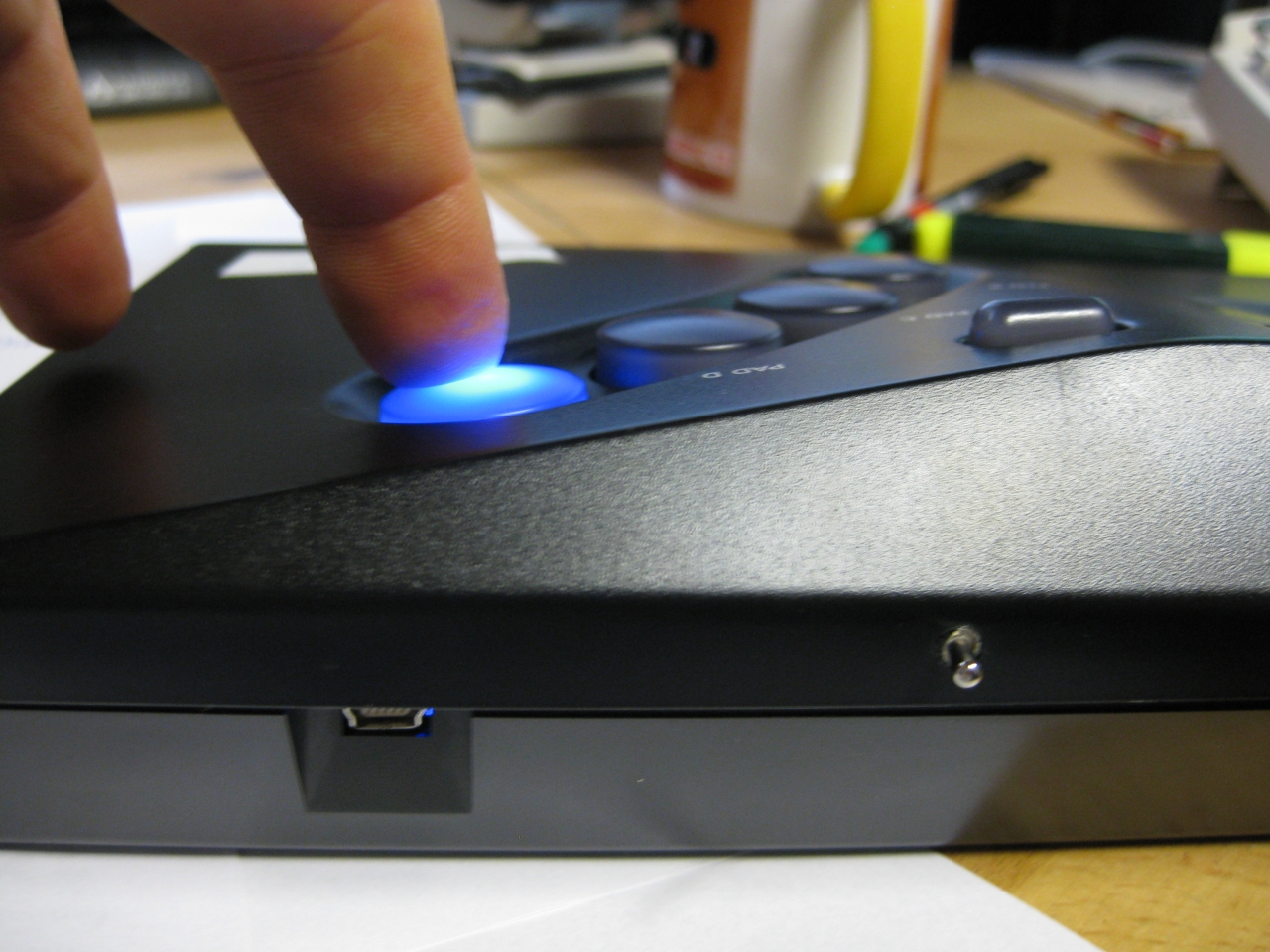
Case Modding for the USB connector and LED
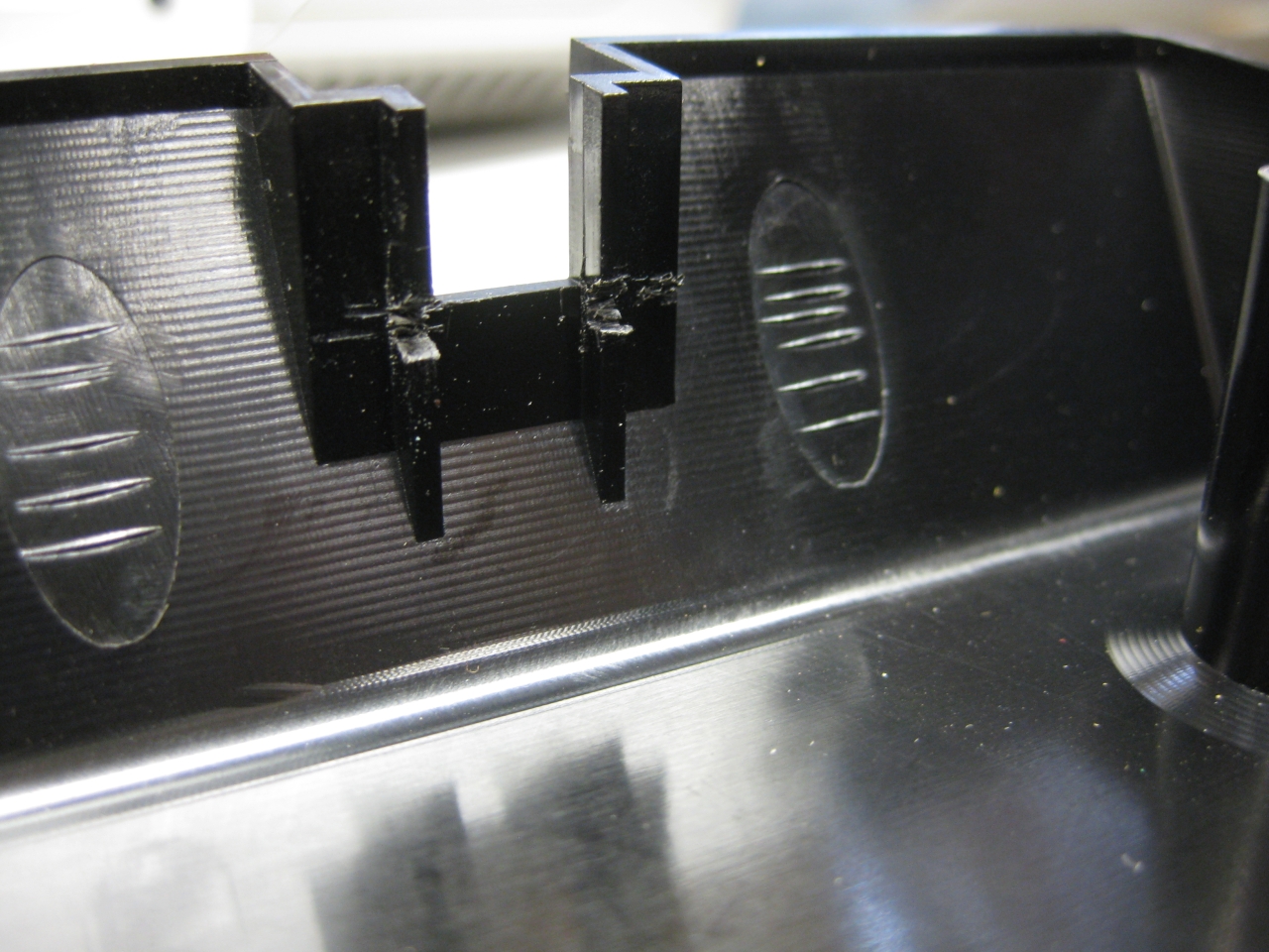
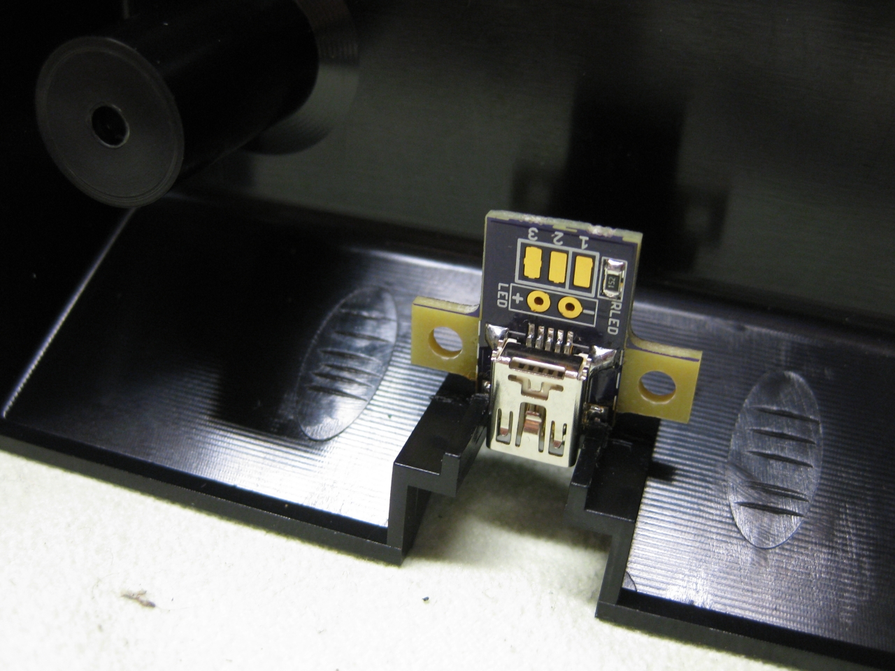
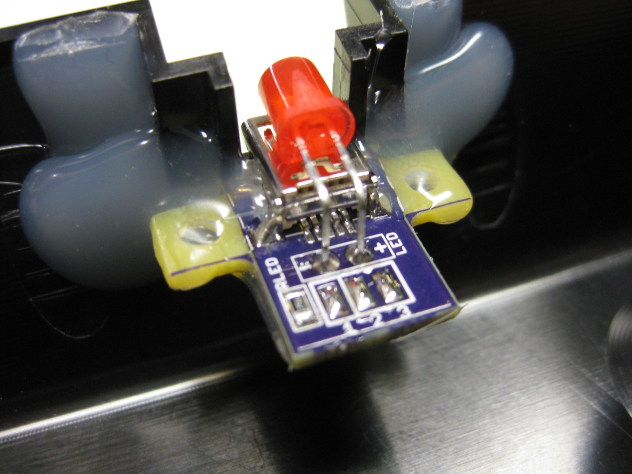
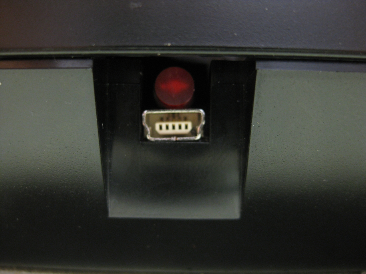
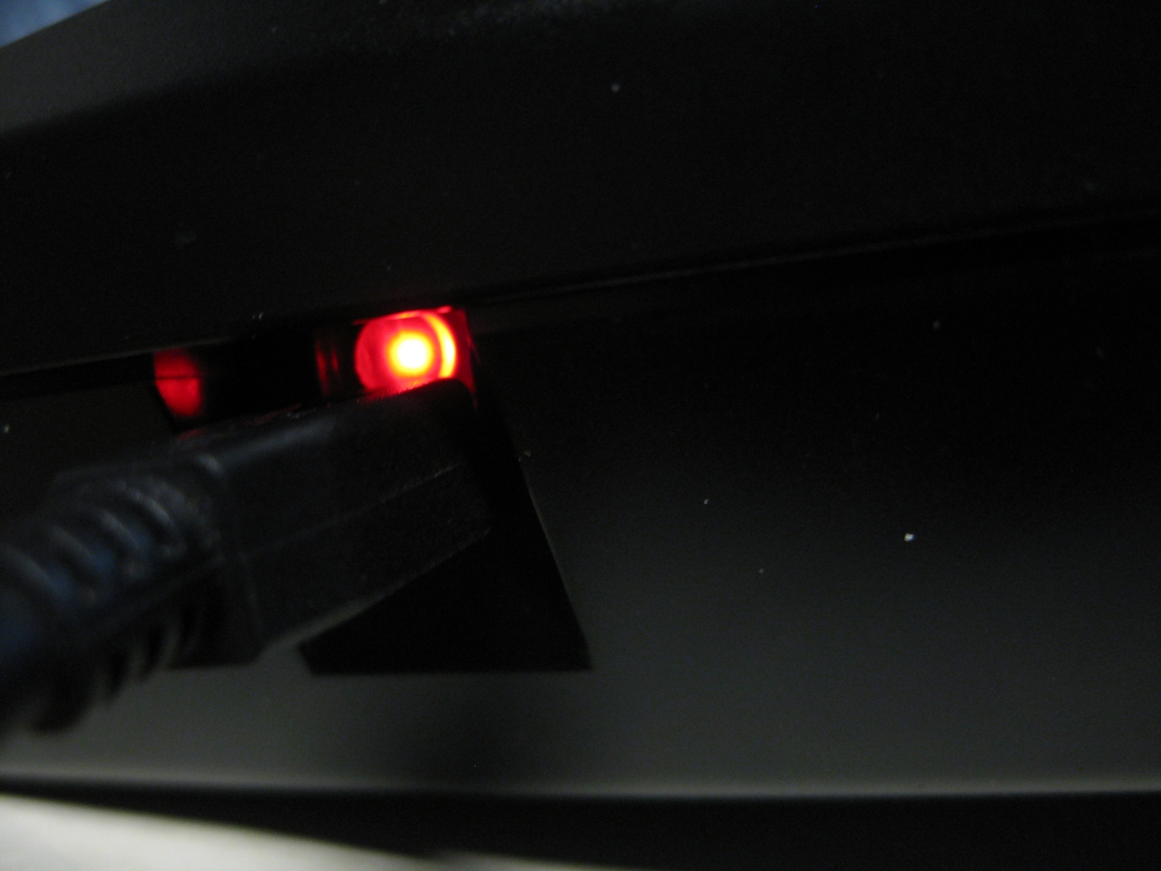
UWRC Part
LiPo Part (you have to change the current load part of UWRC PCB to make it work with a bigger LiPo)
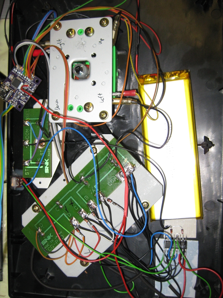
Some Pics
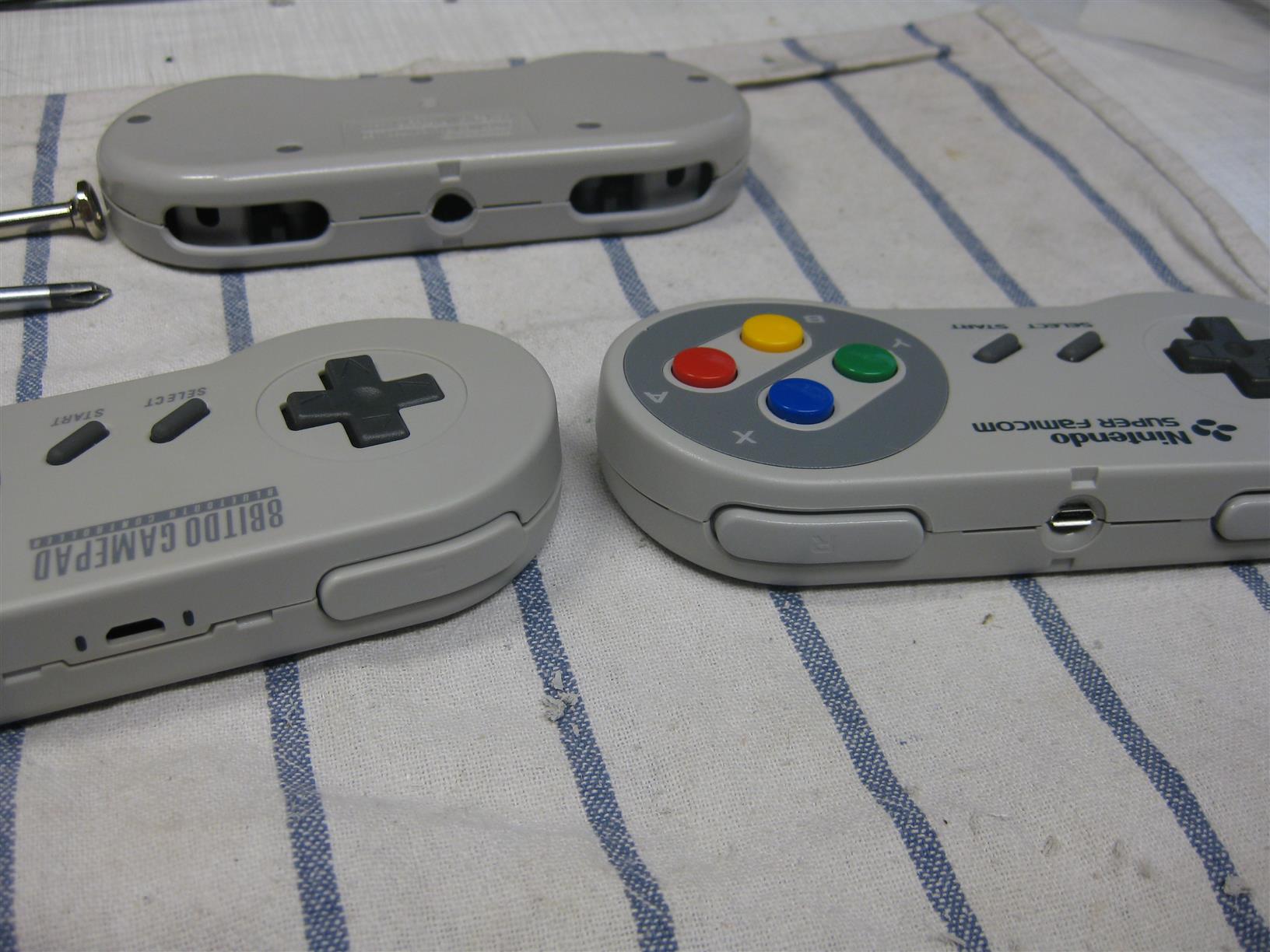
Recently I got some Pads from http://www.8bitdo.com/
If you want to buy some Look here
Great bluetooth Pads working on tablets, iphone, ipad, android phone/tablets, Windows, MAC, Nintendo Wii, Retrocon…
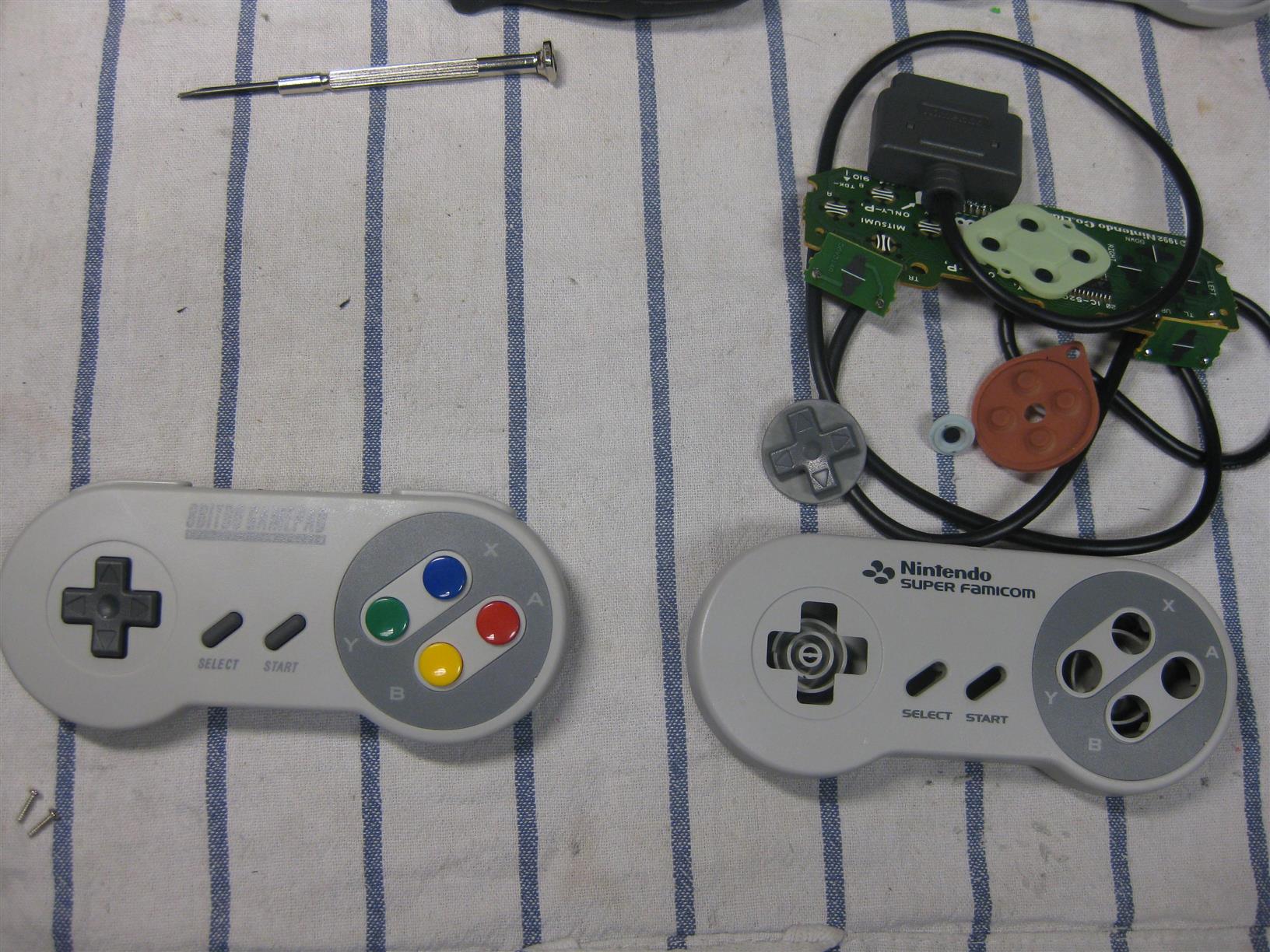
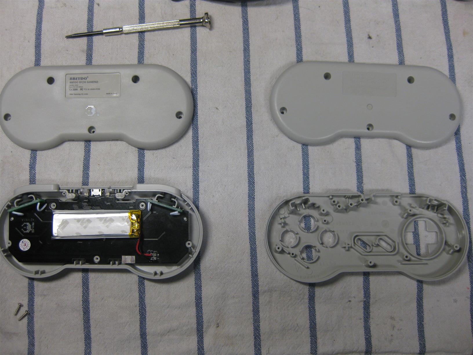
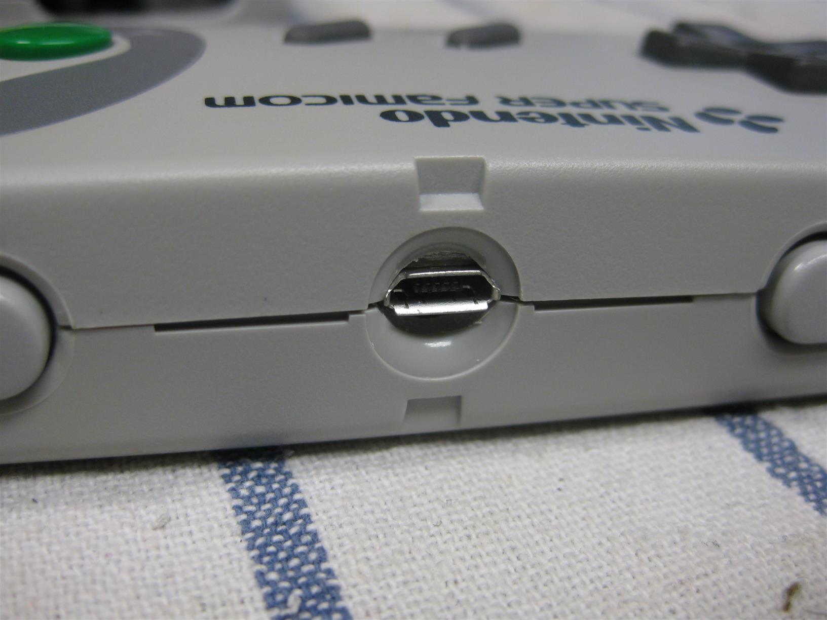
The SFC30 is looking like a SNES Controller and reached it around 80-90%. But I want it 100%
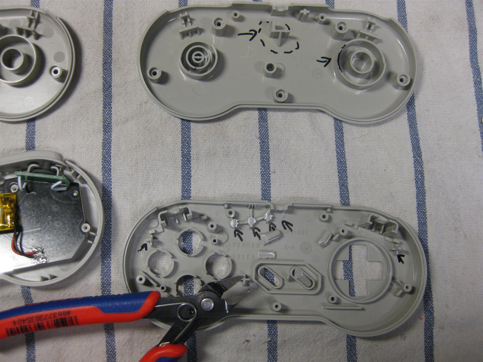
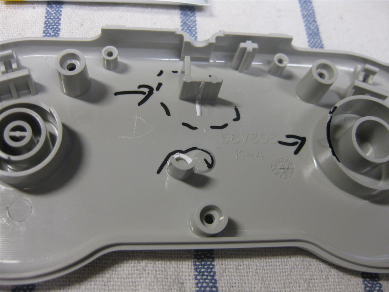
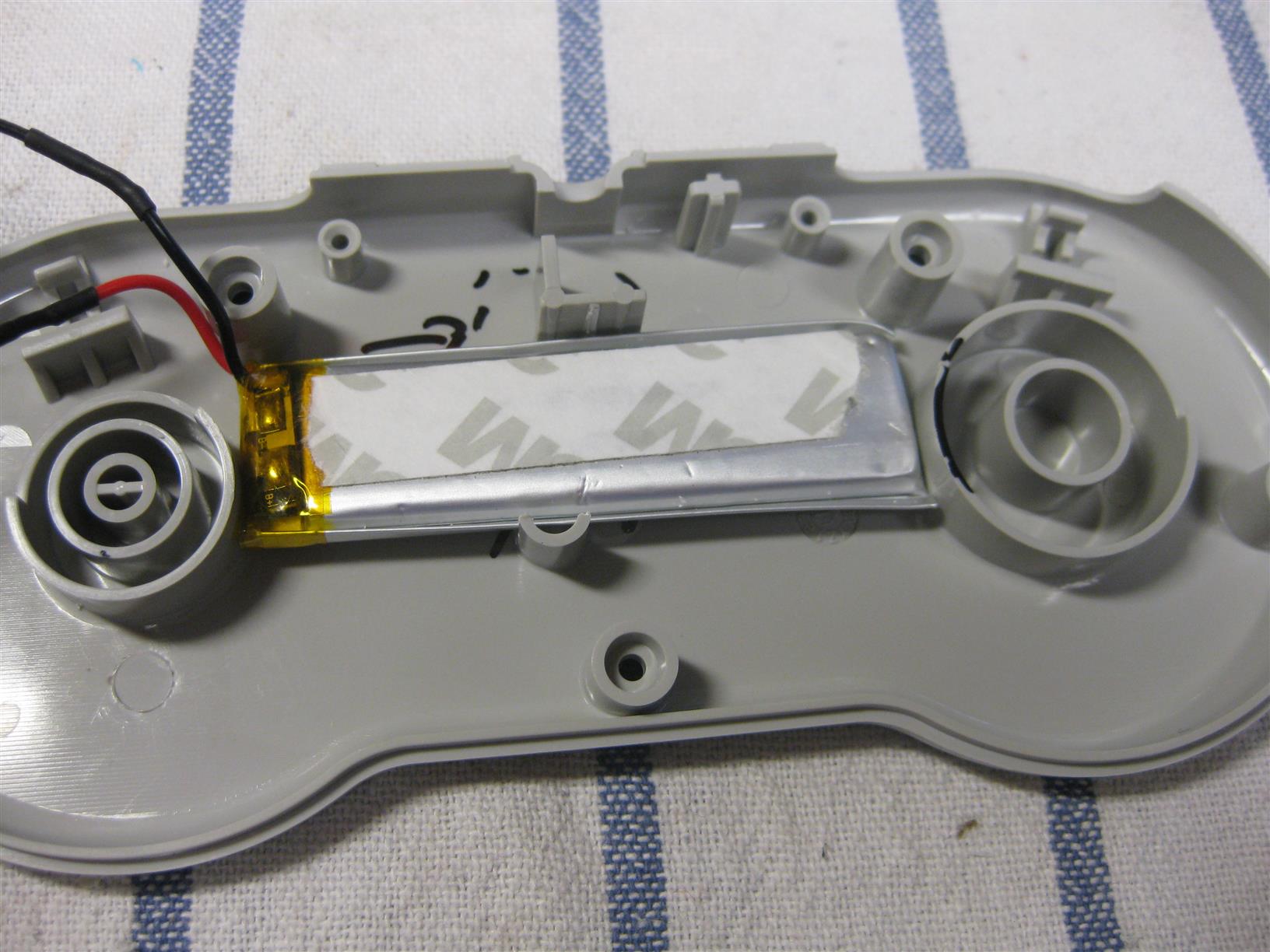
So I put the PCB of a SFC30 into a original SNES Controller. You need only some drilling and its a fast job.
Look here for some pictures during the process
Some month ago I got a lot of uwrc from micro look here:
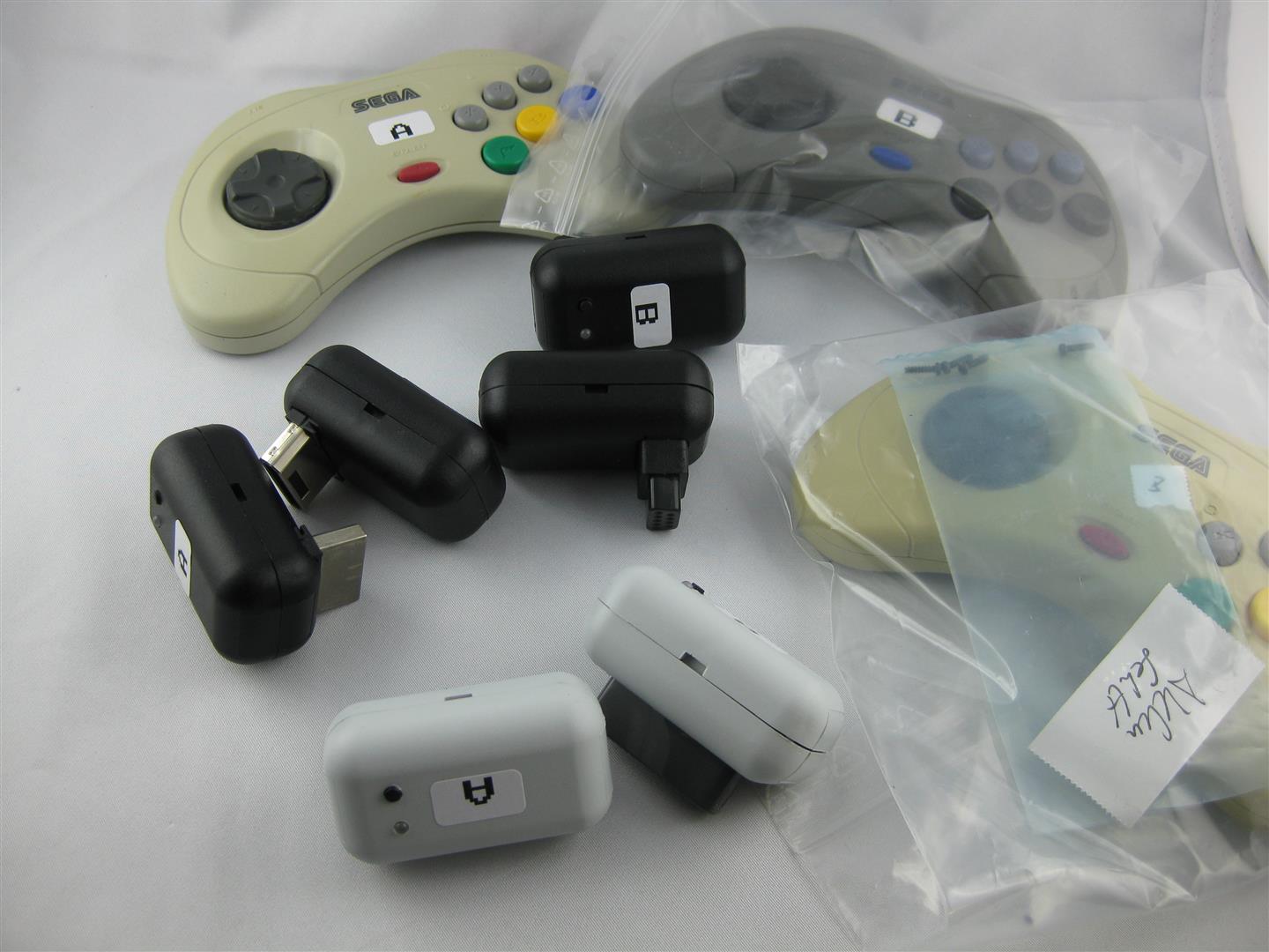
I got some snes, saturn, smd, parts.
and a broken saturn pcb for hacking an old atari 2600 stick (one of my favorite console)
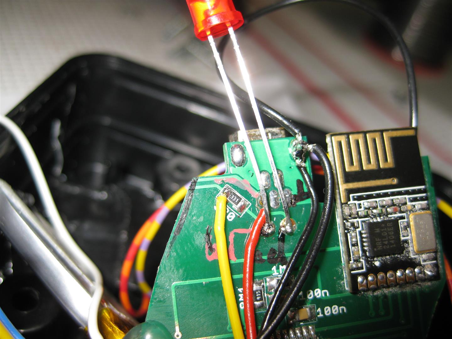
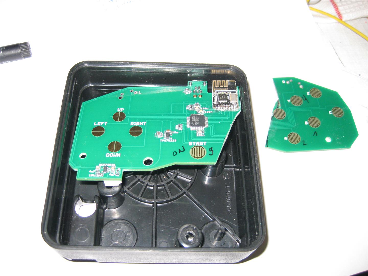
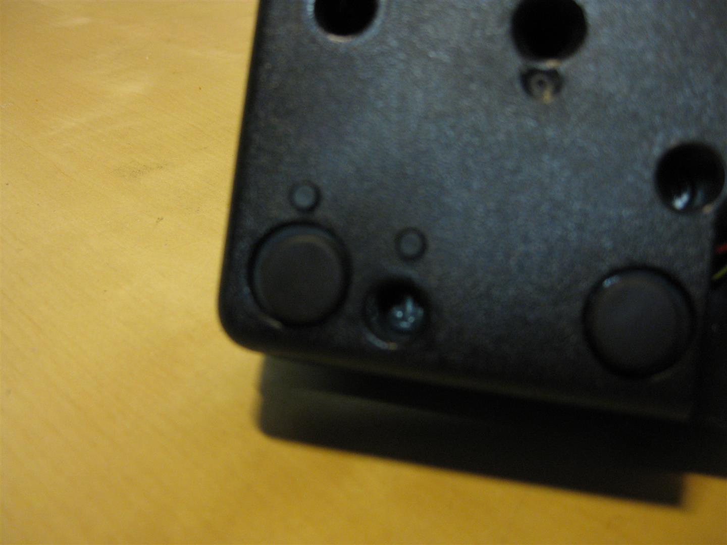
I put some micro switches downunder for start button and 2nd button
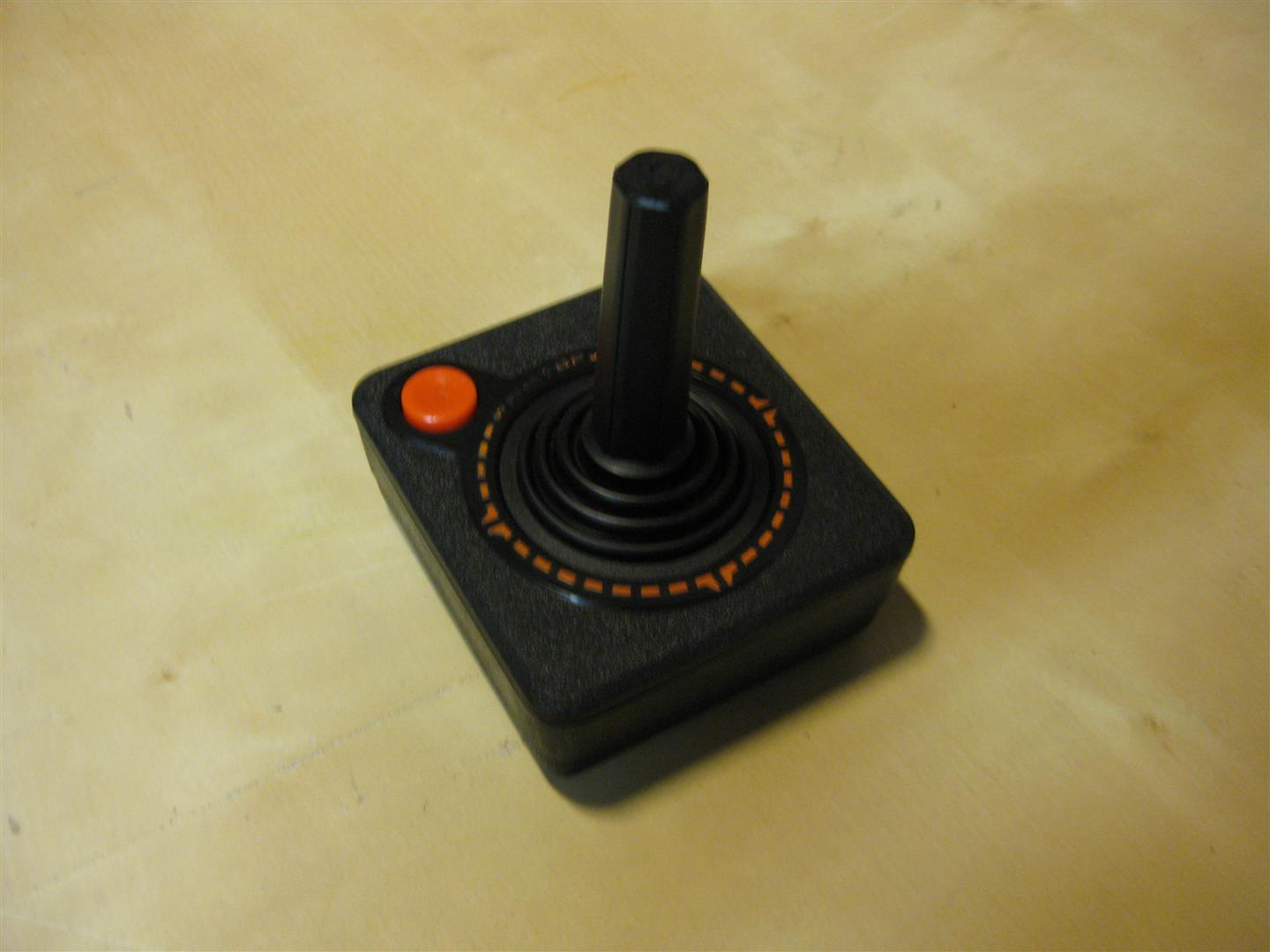
after some time I got my first hacked wirless Atari CX-40 Stick and it looks much better as the atari original
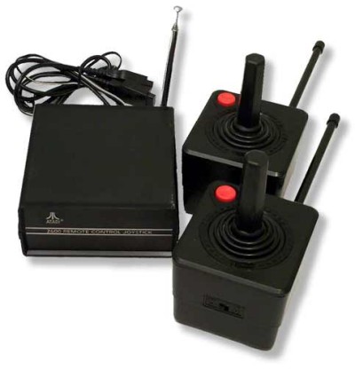
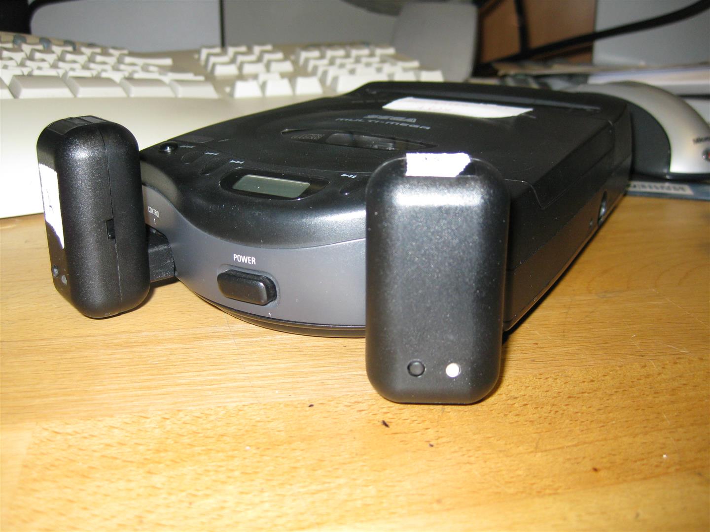
With the help of SegaMegaDrive Receiver all Kind of Controller works with eg:
Sega Master, Sega Mega Drive, Sega MultiMega, Atari 800, Atari 800XE, Atari 800XL Atari 2600, Amiga, Atari ST, Commodore C64 🙂
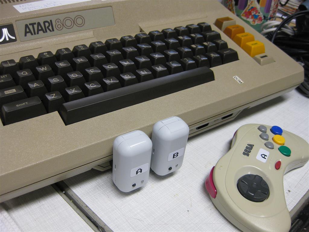
I used a Retro-Adapter and a SNES Receiver from micro, to make the UWRC work with usb for PC Emulator using.
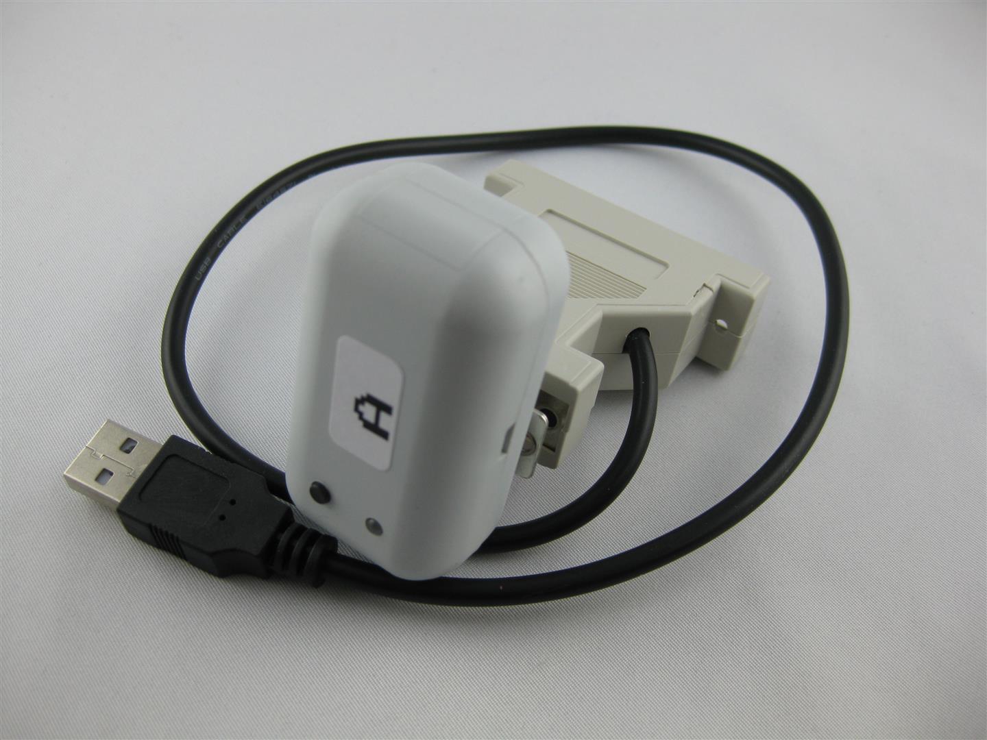
Now I can use all kind of controller at the original Consoles and PC
I am currently have Controllers:
4x UWRC Saturn Controllers
1x UWRC SNES Controller (micro I need more, please make a new batch of pcbs)
1x UWRC Atari CX-40 Controller
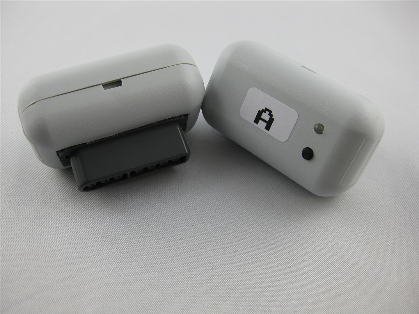
Receiver:
some Saturn Receiver
2x Neo Geo Receiver
Snes Receiver
After all, gaming wireless is the best thing happens to my old consoles since years
thanks to micro to make this possible
look here for a snes looking not good
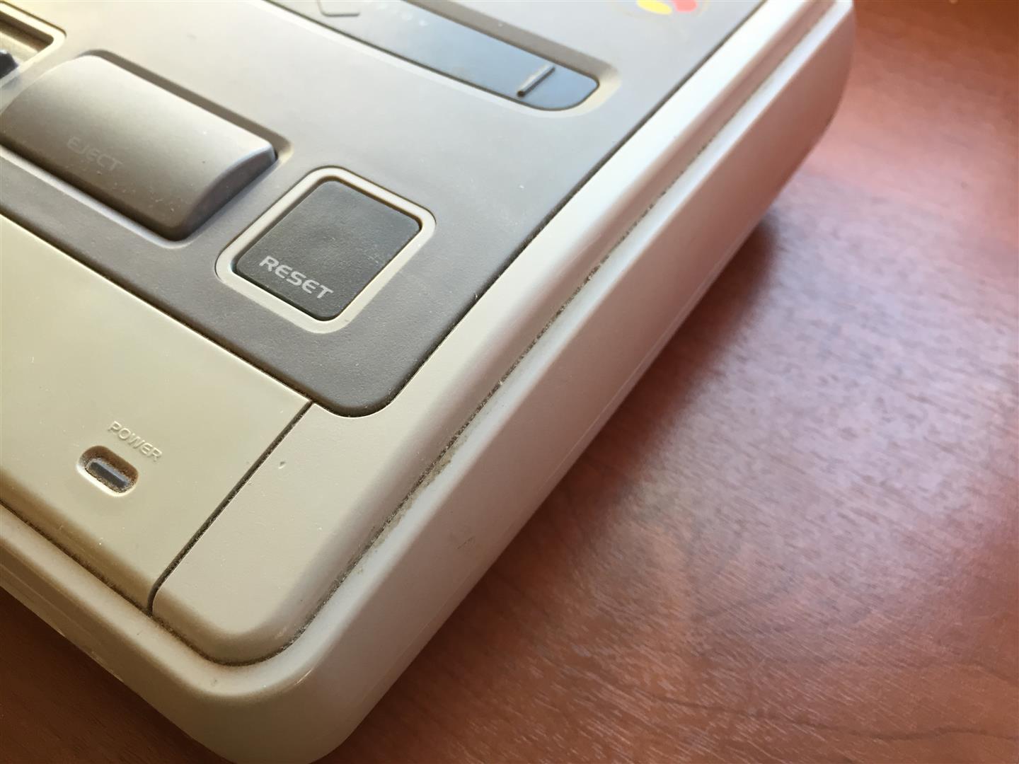
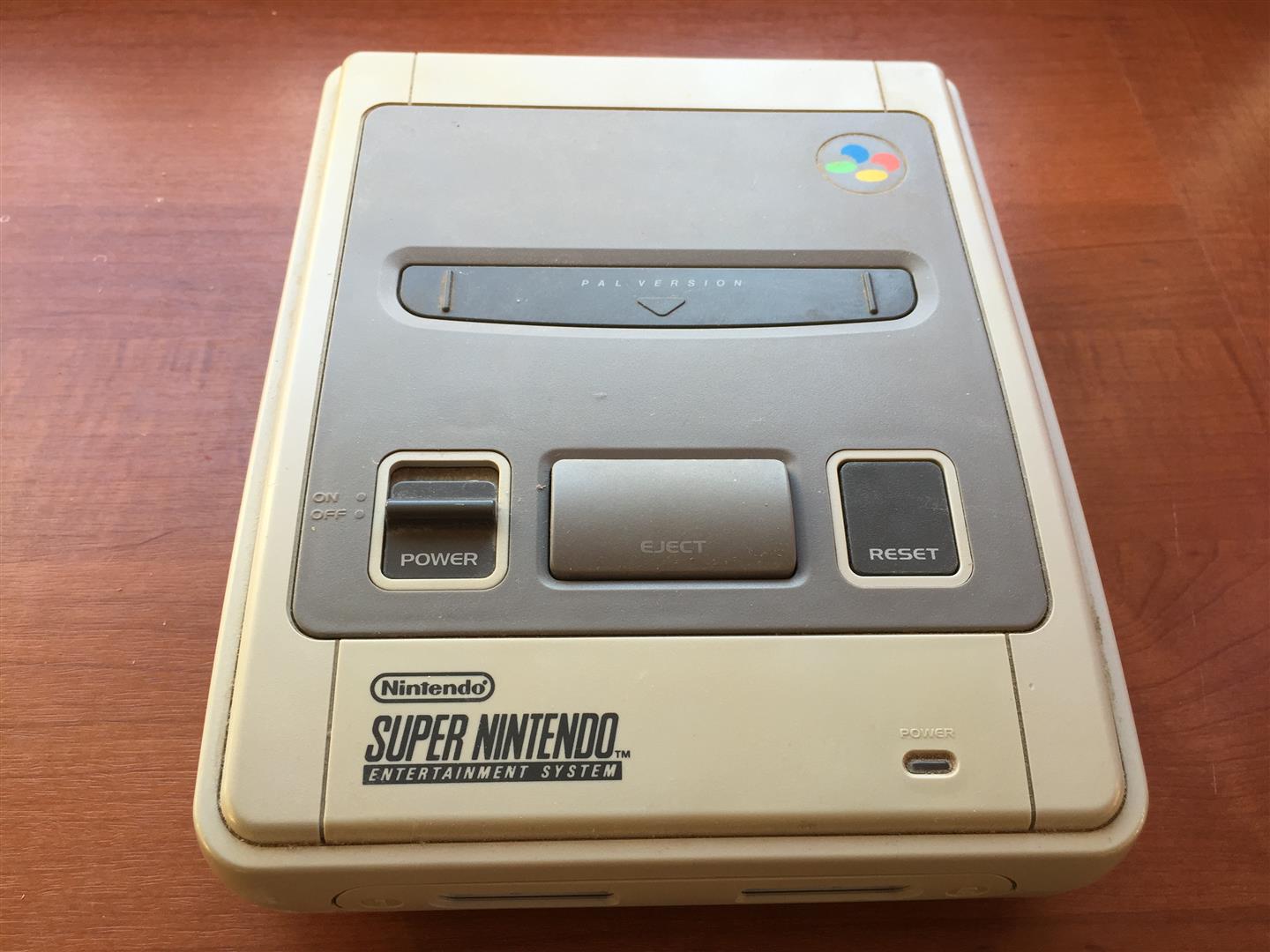
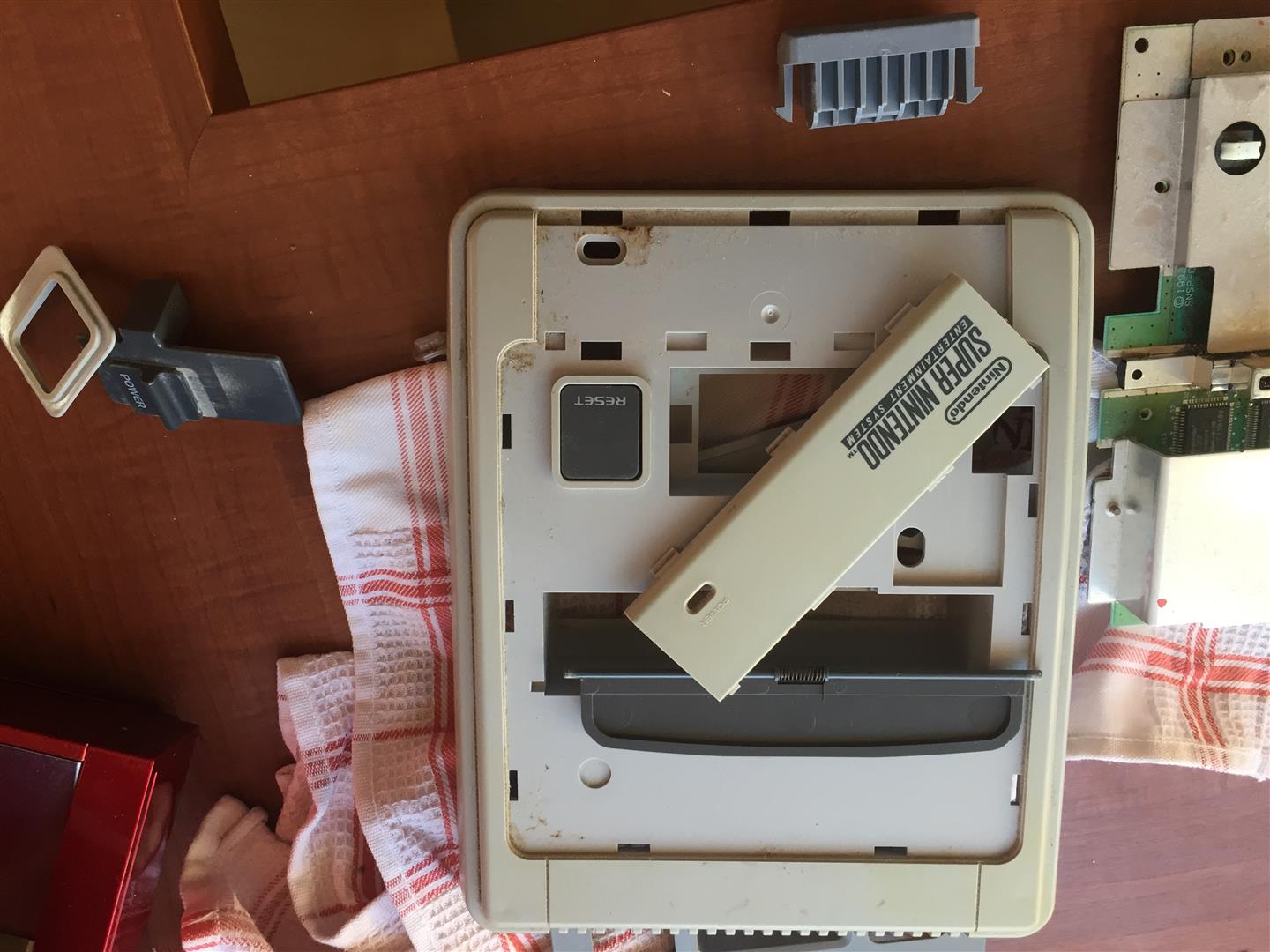
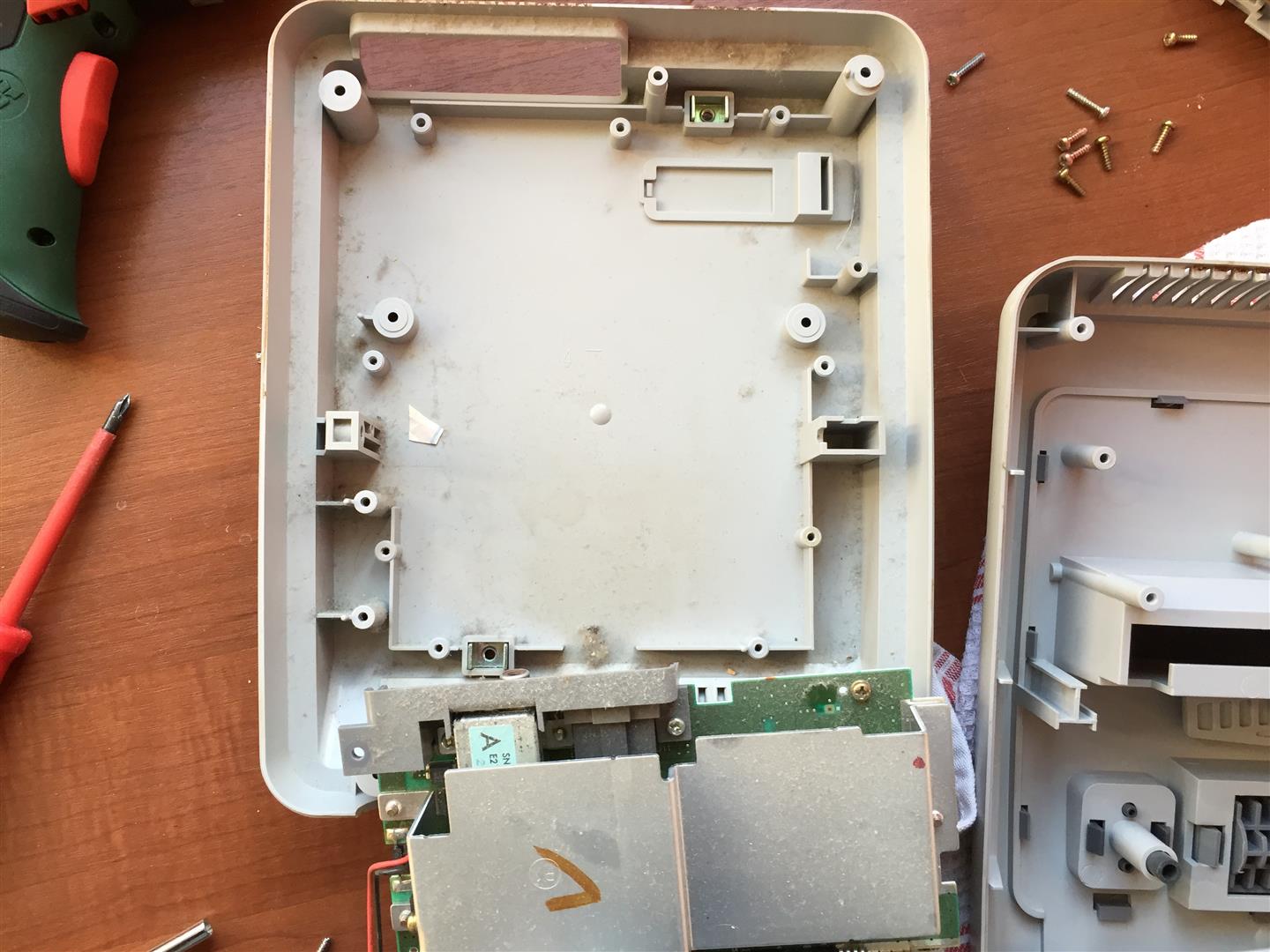
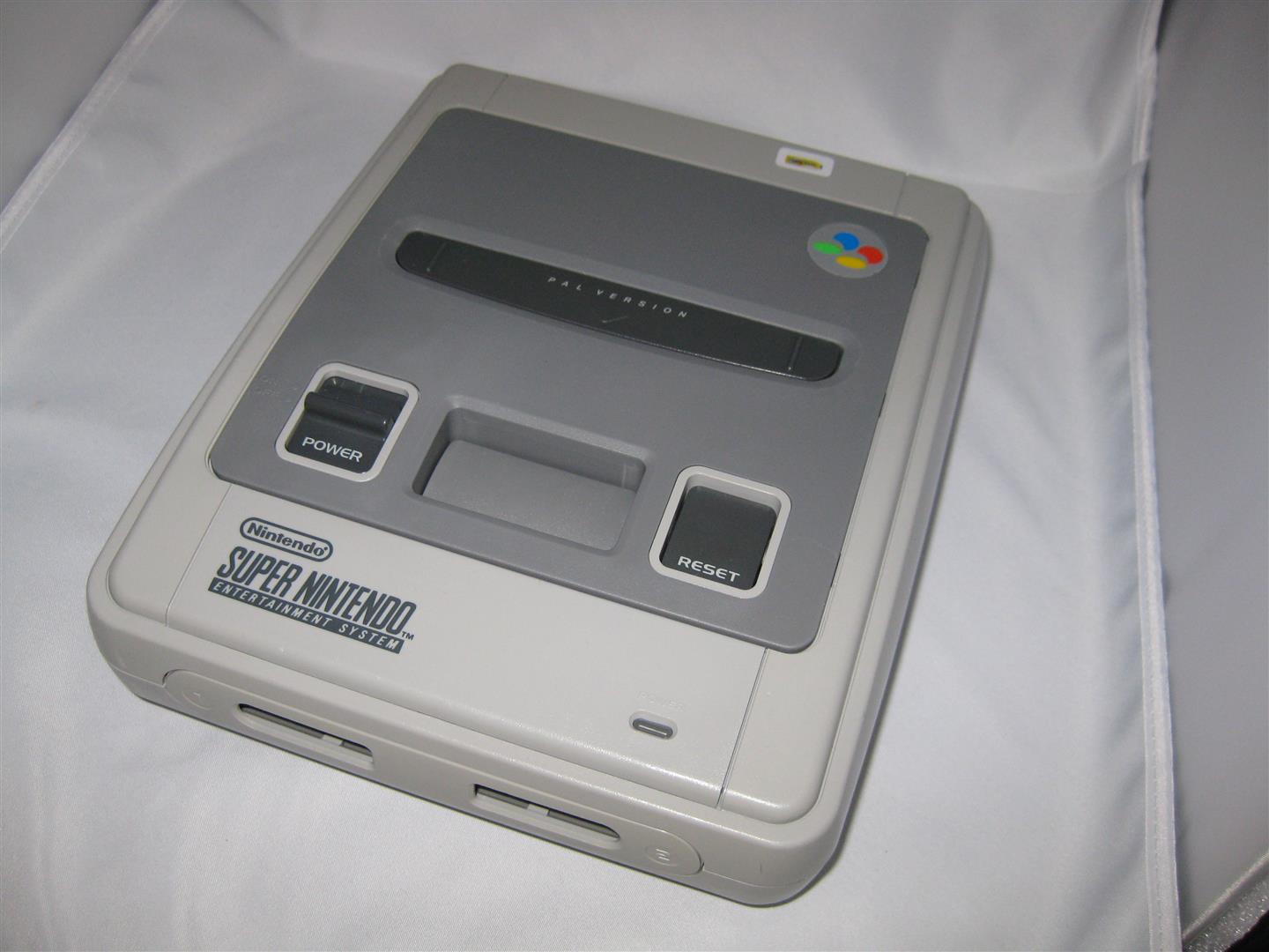
After some cleaning and 1-2 weeks in sun and a retrobright lotion it looks really nice again
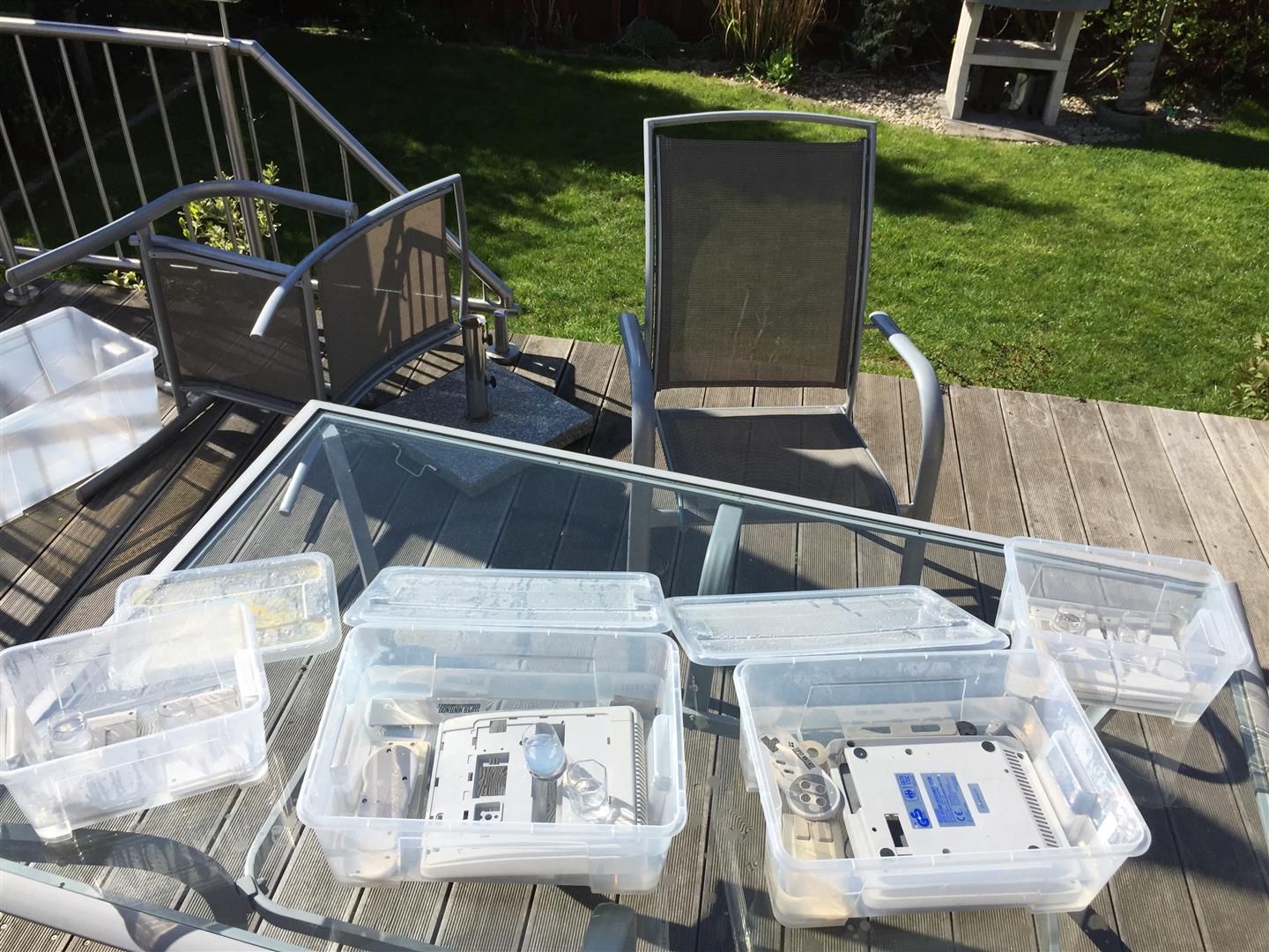
final
I am in search for a nice Harddisc Case in white, but I didn’t find any nice looking case…
After this I decided to put a 3,5Zoll Sata Harddisc into a broken Wii.
I am planing to use the original Power Supply and the original USB Connectors.
")
I opened the wii and removed all until you only have the main PCB inside
I removed to parts (red marked) to disable the USB Wires into the mainboard and connected the USB Cables from the USB/Sata Connector to the onbaord USB Port
")
The power is taken from the Top Site of the mainbaord. Here I have to remove the original Fuse (red marked) to avoid getting any voltage to the mainboard.
You can get 12V to power up harddisc from the right site of the fuse.
GND is found at the edge of the mainboard.
I placed a standard 7805 voltage regulator to get the 5V for the Harddisc
")
Here you can see original case of the used USB/Sata Connector
")
all together
")
I extended the power Led of the USB/Sata Adapter to the original power LED of the wii
")
And here you can see the final backsite with connectors
")
 ,
,