Kategorie: Atari

  • the!cart and the right case

    finaly I got the!cart and it needed the right home.

    With the help of a cutter knife, dremel and hotglue it fits into a classic Atari 800 Cartridge.

    the!cart (1)

    the!cart (2)

    the!cart (3)

    the!cart (4)

    the!cart (5)

    the!cart (6)

    7mm height

    the!cart (7)

    the!cart (8)

    the!cart (9)

    the!cart (10)


    the!cart (11)


    compare_a800Carts


    Label in Atari 400/800 Style

    THE!CART – Font: Salzburg-Bold
    COMPUTER GAMES – Font: Salzburg-Regular
    USE WITH CONSOLE… – Font: Salzburg-Bold
    CXL4042 – Font: HammerFat


    THE!CART_CXL4042_Label_Dark_Background_white_text_width_5,59cm


  • Atari sio2sd in a Atari 1064 case

    I bought a cheap sio2sd and put it into a Atari 1064case.

    Inspired from http://atariage.com/forums/topic/175988-new-case-for-my-sio2sd/

    Some dremel, hotglue and time…

    sio2sd_atari_1064case_1

    sio2sd_atari_1064case_4

    sio2sd_atari_1064case_3

    sio2sd_atari_1064case_2

  • Atari 800 and Flash Cartridges

    when using The!Cart or MyIDE II with atari you need to do a mod of some signals

    Reference: https://www.wudsn.com/index.php/productions-atari800/tools/thecart/atari-800-fix

    Only Cut one circuit and add a wire and you are done

    atari 800 solder side fix

  • One Power Supply to rule them all

    For testing old Computers you will need a lot of different power supplys with AC and DC Voltage.

    I put them together and we got one to rule them all 😉
    Meanwell RT-65B and a 9V AC Power Supply

    9V /2100mA
    5V / 5,0A
    12V / 2,8A
    -12V /0,5A

    So it works @:

    • Atari 8 Bit Computer like 600XL, 800XL, 1200XL, 800XE, 64XE, 130XE
    • Atari 8 Bit Computer like Atari 400, 800, Atari 810, Atari 1050
    • Commodore C64, C16, C64C
    • Commodore Amiga 500,500Plus, 600,1200
    • Commodore CD32, Commodore 1541 II
    • Neo Geo 5V Unit

    power_one_to_rule_them_all (8)

    power_one_to_rule_them_all (7)

    power_one_to_rule_them_all (5)

    power_one_to_rule_them_all (1)

    power_one_to_rule_them_all (2)

    power_one_to_rule_them_all (4)

  • Atari 600XL RAM Ugrade to 64MB

    Its time to bring up this little beauty to the level of a Atari 800XL.

    An easy mod, because all parts in a Atari 600XL are socket and you  only need to change 2 RAM Chips and do some wiring

    Works with Pal and here shown NTSC Version

    Remove U11 and U12 (was: TMS 4416-15NL 4bitx16k)

    Replace with : MCM41464 AP10 (4bitx64k)
    or : NEC D41464C-10 (4bitx64k)
    OR : HMS50464P (4bitx64k)
    or : any 4464 equialent (4bitx64k)

    Wire Lifted DownSide R36 to Lifted U16 Pin 08

    Wire Lifted U5 Pin 03 to U9 Pin 21 Dia Nearby

    Wire Lifted U6 Pin 10 to U9 Pin 22 Dia nearby

    a600_XL_RAM_Upgrade_1


    Atari600XL_Ram_Upgrade_to_64MB


  • Atari 800 RGB Mod via Sophia

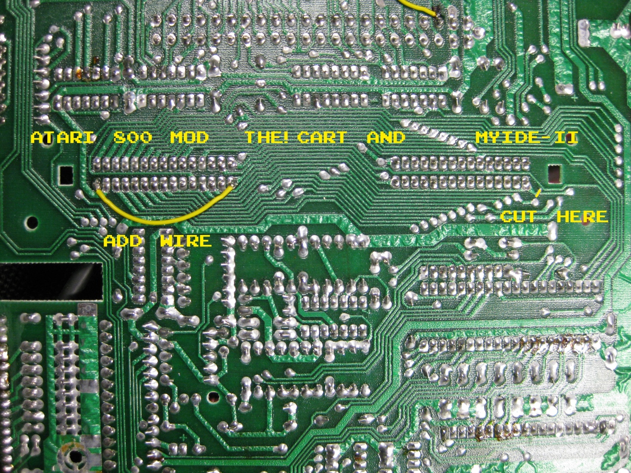
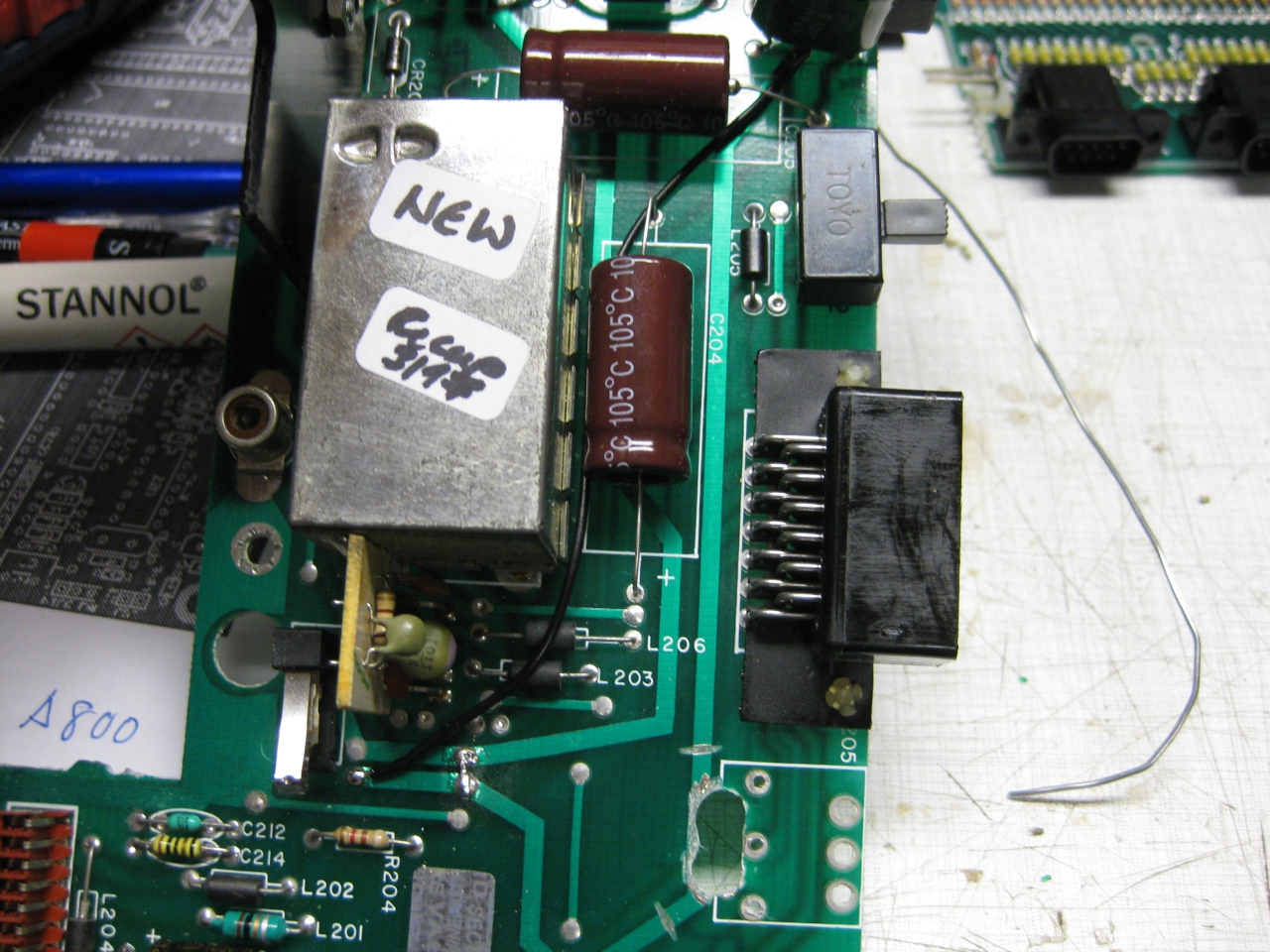
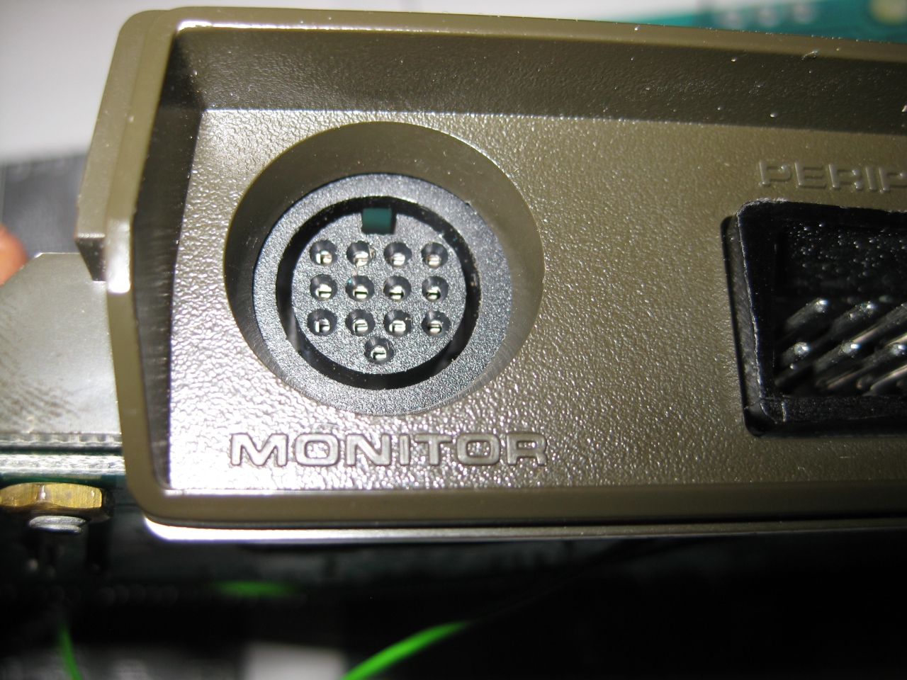
    Atari 800 was my first computer after Sinclair ZX81 and its time to make the picture better. After checking the A/V Out it contains Video and S-Video in a good qualitiy. So i decided to replace the original DIN Connector and replace it with a DIN 13 like used in Atari 7800 french and Atari ST. I used some not needed pins from the Din 13 to put in Video and S-Video too. So its possible to use RGB-Output via a standard french Atari 7800 RGB Cable and with a special Cable made I can use Video and S-Video too via the same connector.

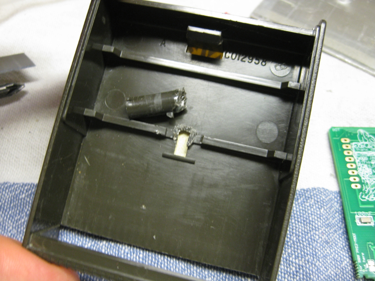
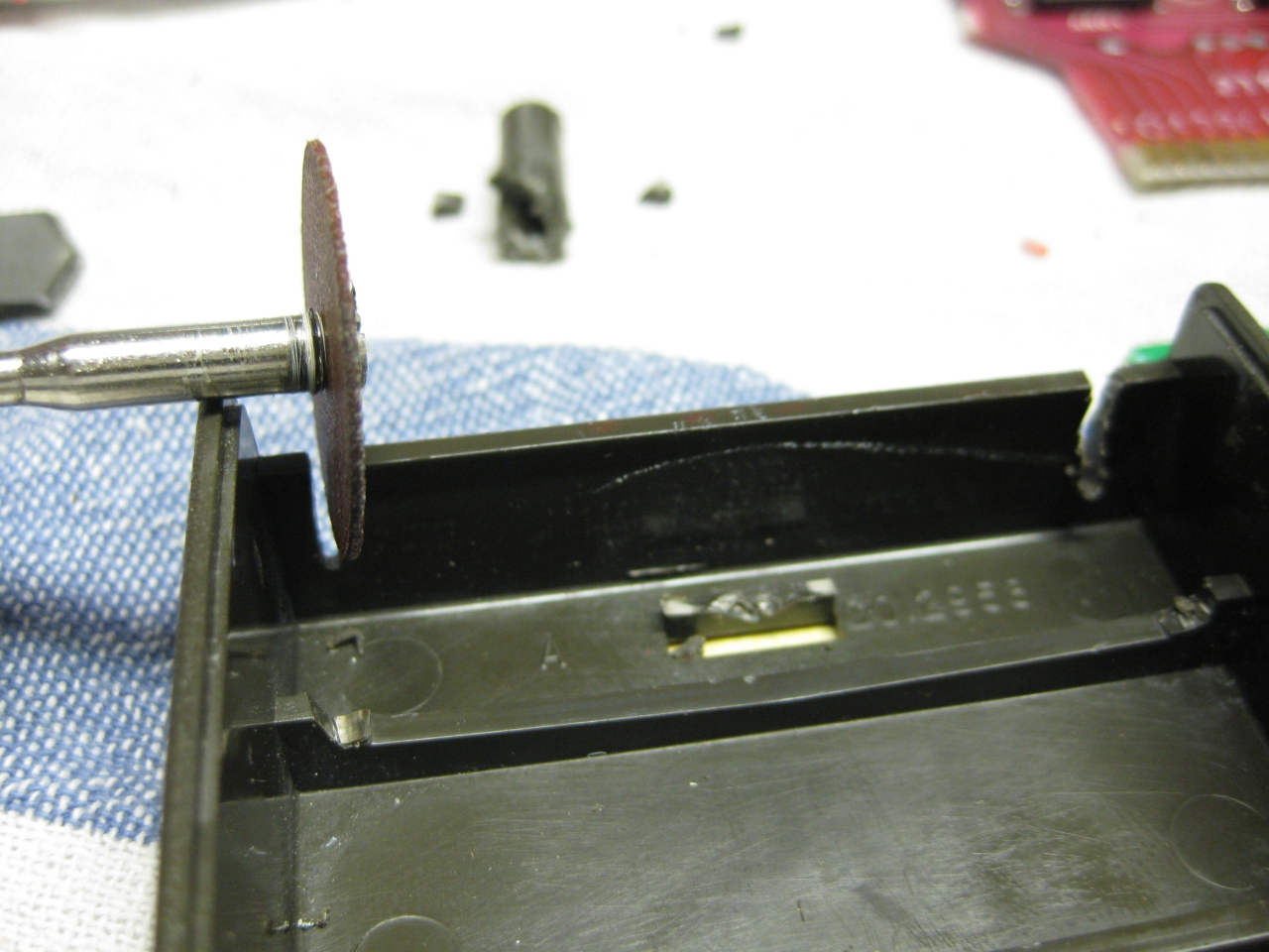
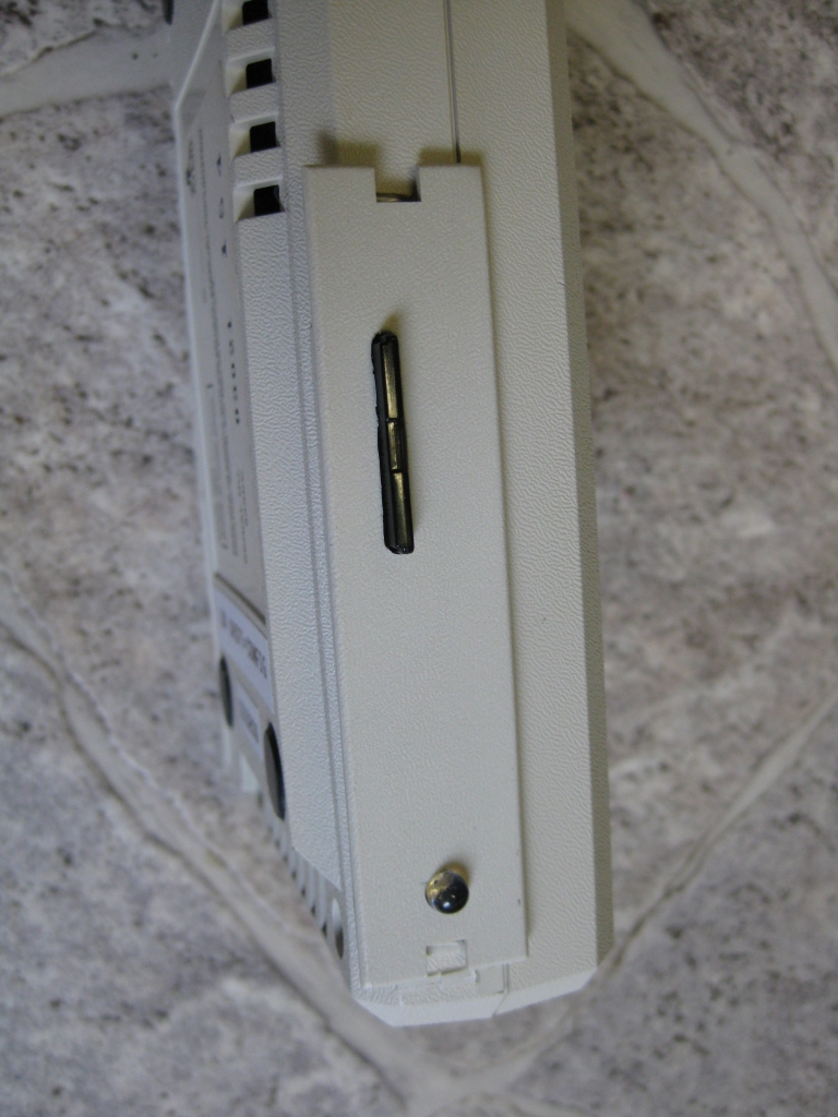
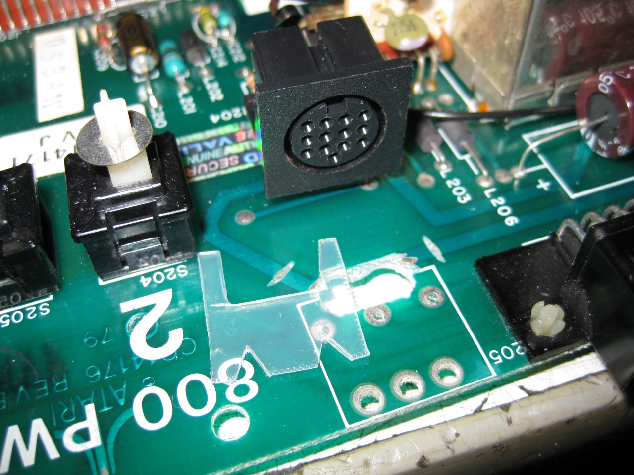
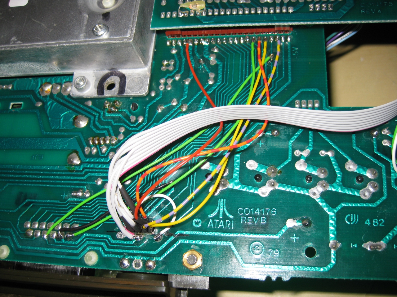
    To put the DIN 13 in the right position i need some plastic and drilled holes downunder to make the Din connectors accessable


    a800_sophia (5)

    a800_sophia (6)

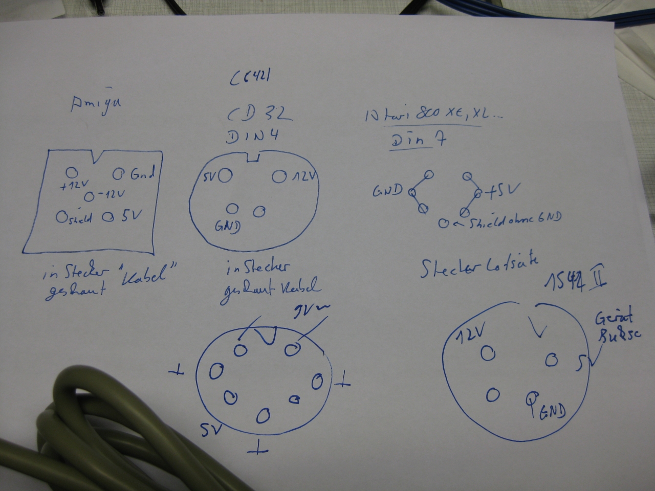
    replaced DIN 5 to DIN13
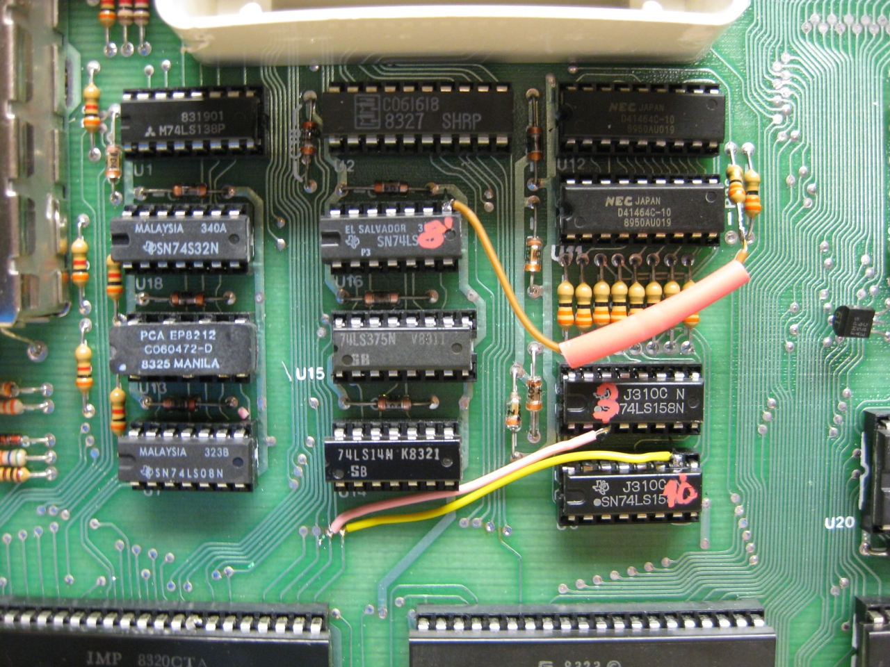
    a800_sophia (4)

    downunder chaos

    a800_sophia (2)

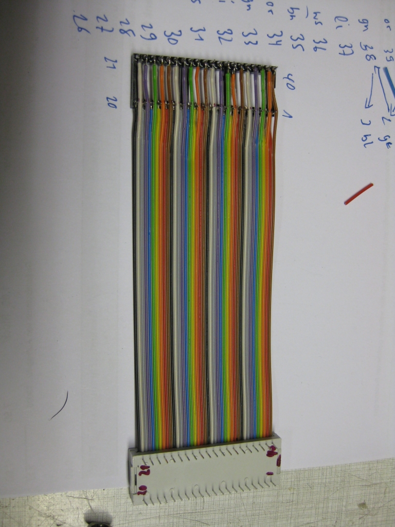
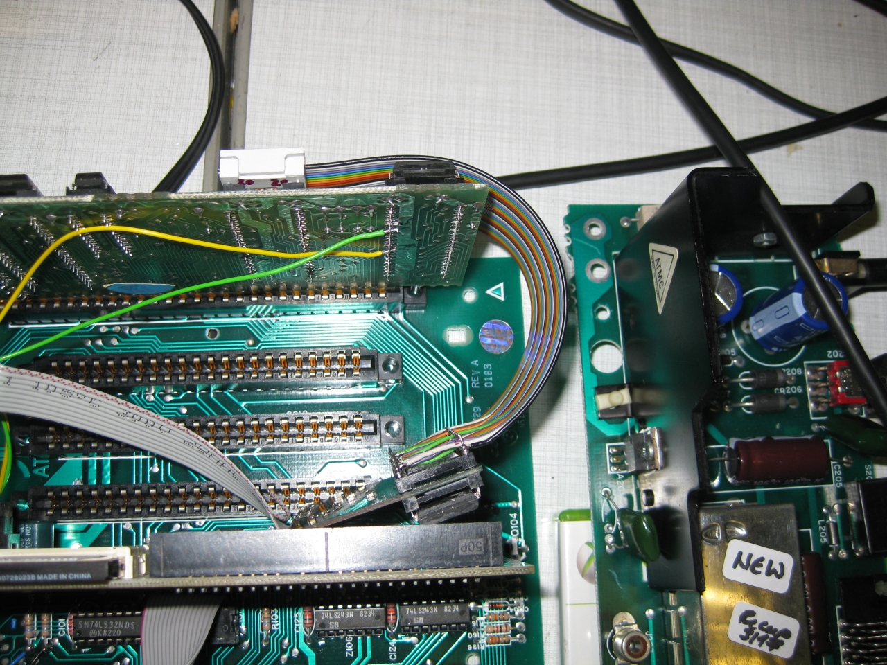
    because of no space at the CPU Board I needed to move the Sophia Board to another place. I uses some ribbon extension like this

    a800_sophia (1)

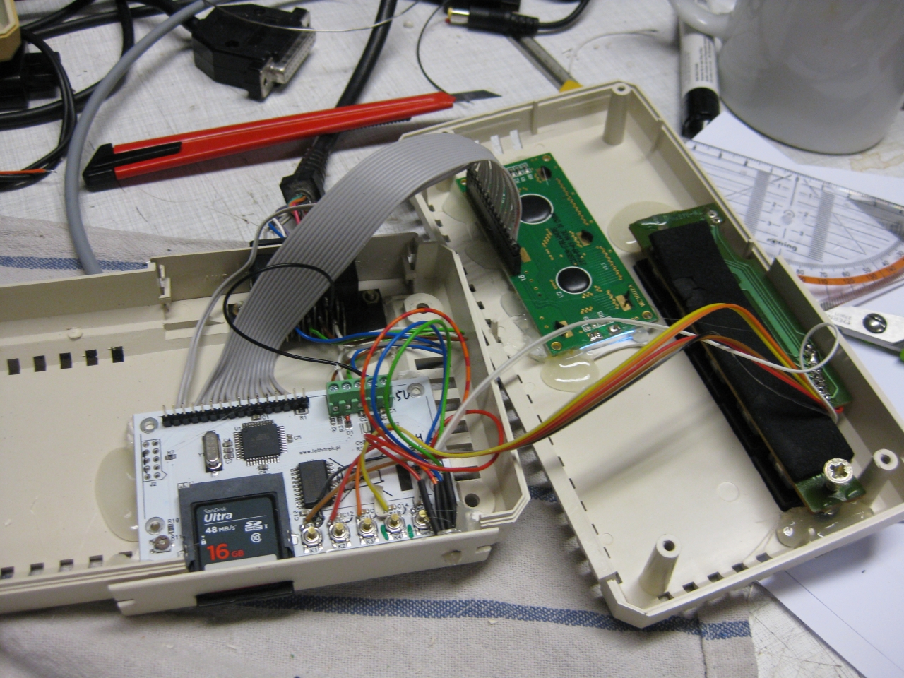
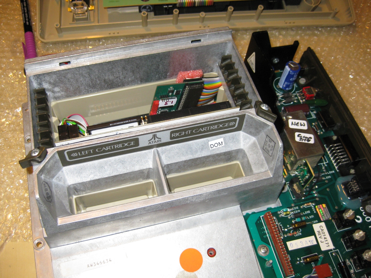
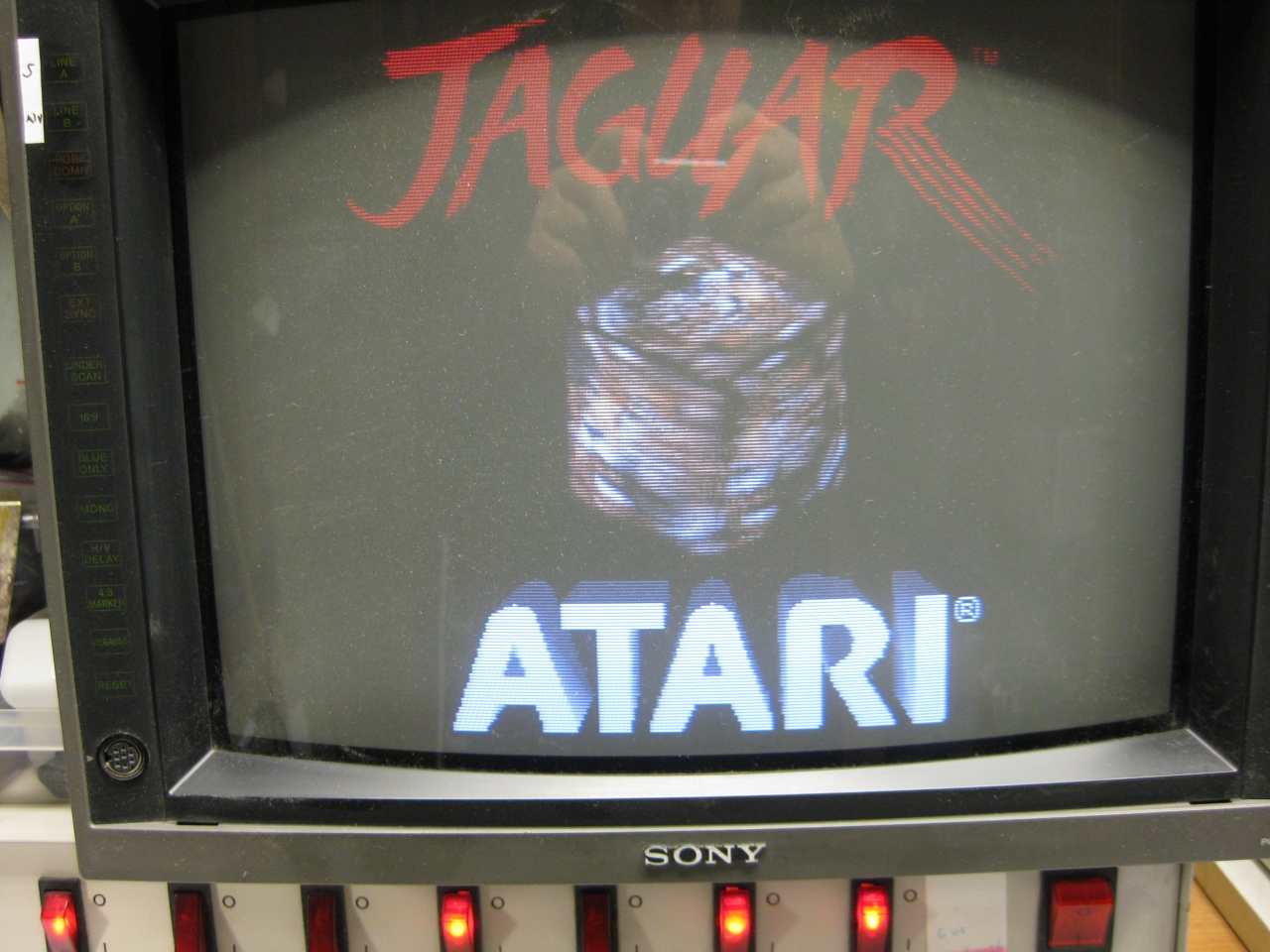
    and here we go. In front you see incognito board too 🙂

    a800_sophia (7)

    after finishing up it looks like this

    a800_sophia (3)

  • Atari Jaguar „switchless“ + Reset Addon + Multibios


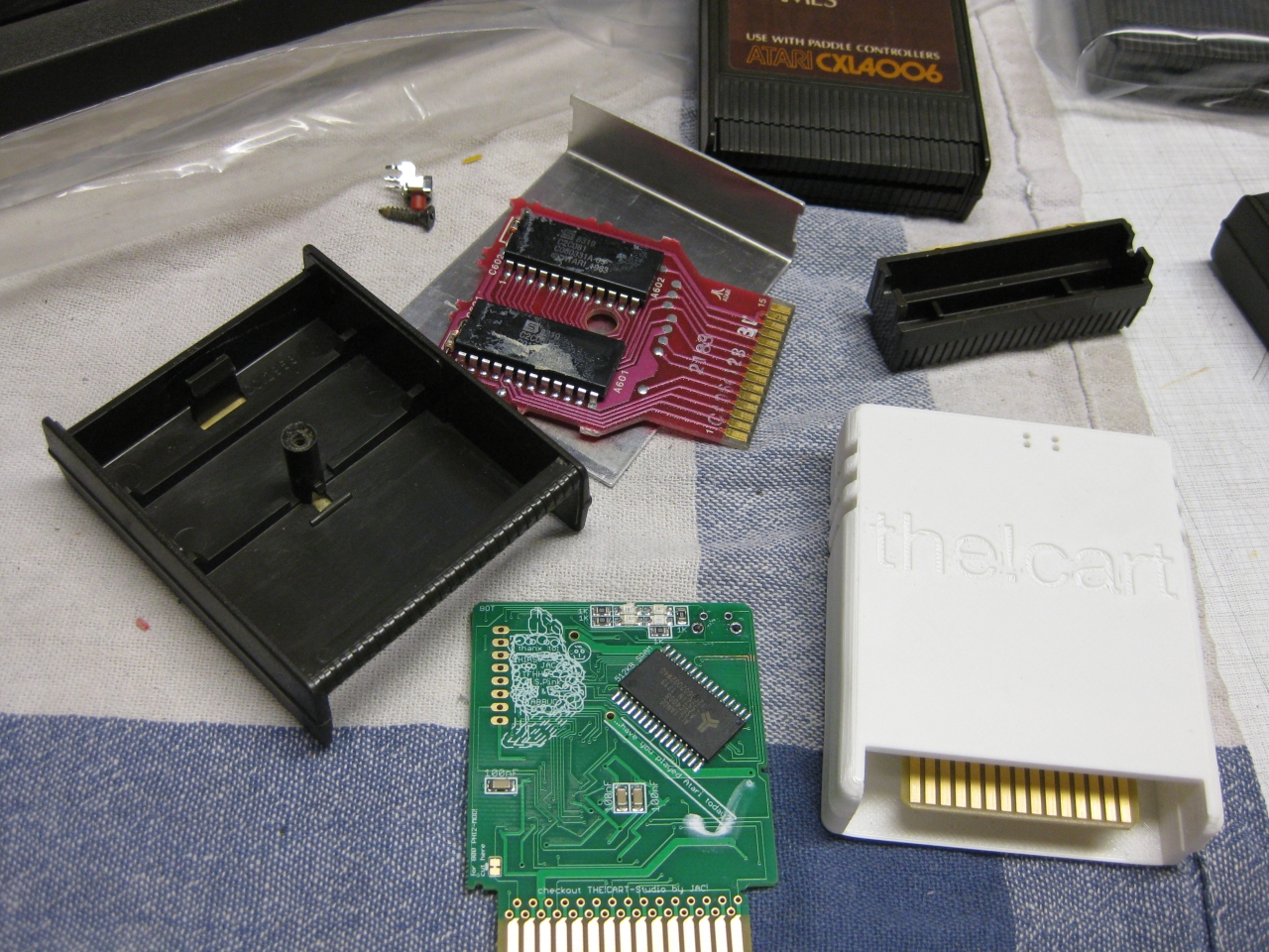
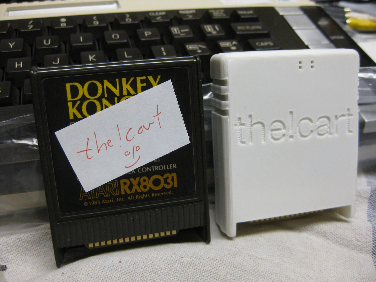
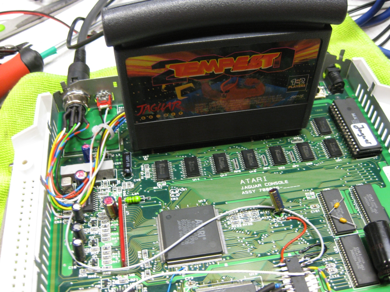
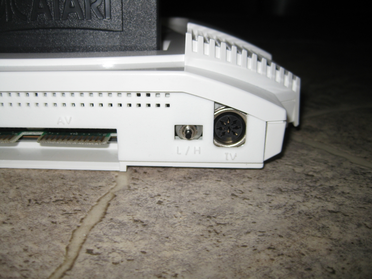
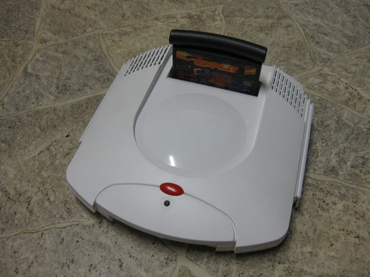
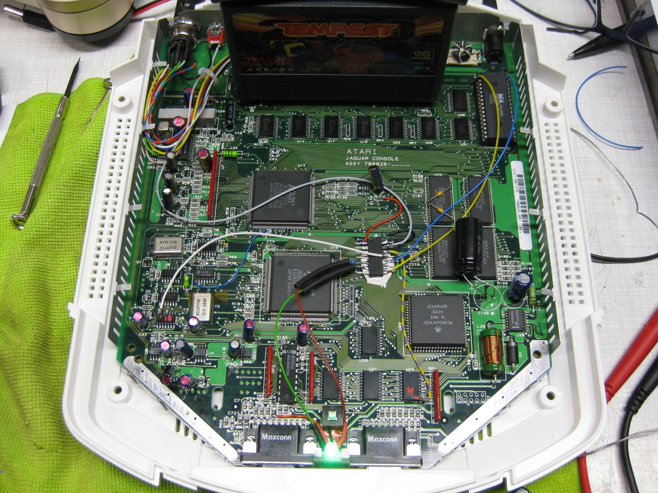
    I got a white „dental“ case and its time to make the jaguar ready for 2017 😉

    The title is something strange, but its comming from a Sega Saturn Mod years ago (the code is based on this). The Saturn reset button is used for change region and 50/60Hz.

    Jaguar_RGB_Led_switchless

    You will need:
    -pic16f630
    -button
    -RGB-Led

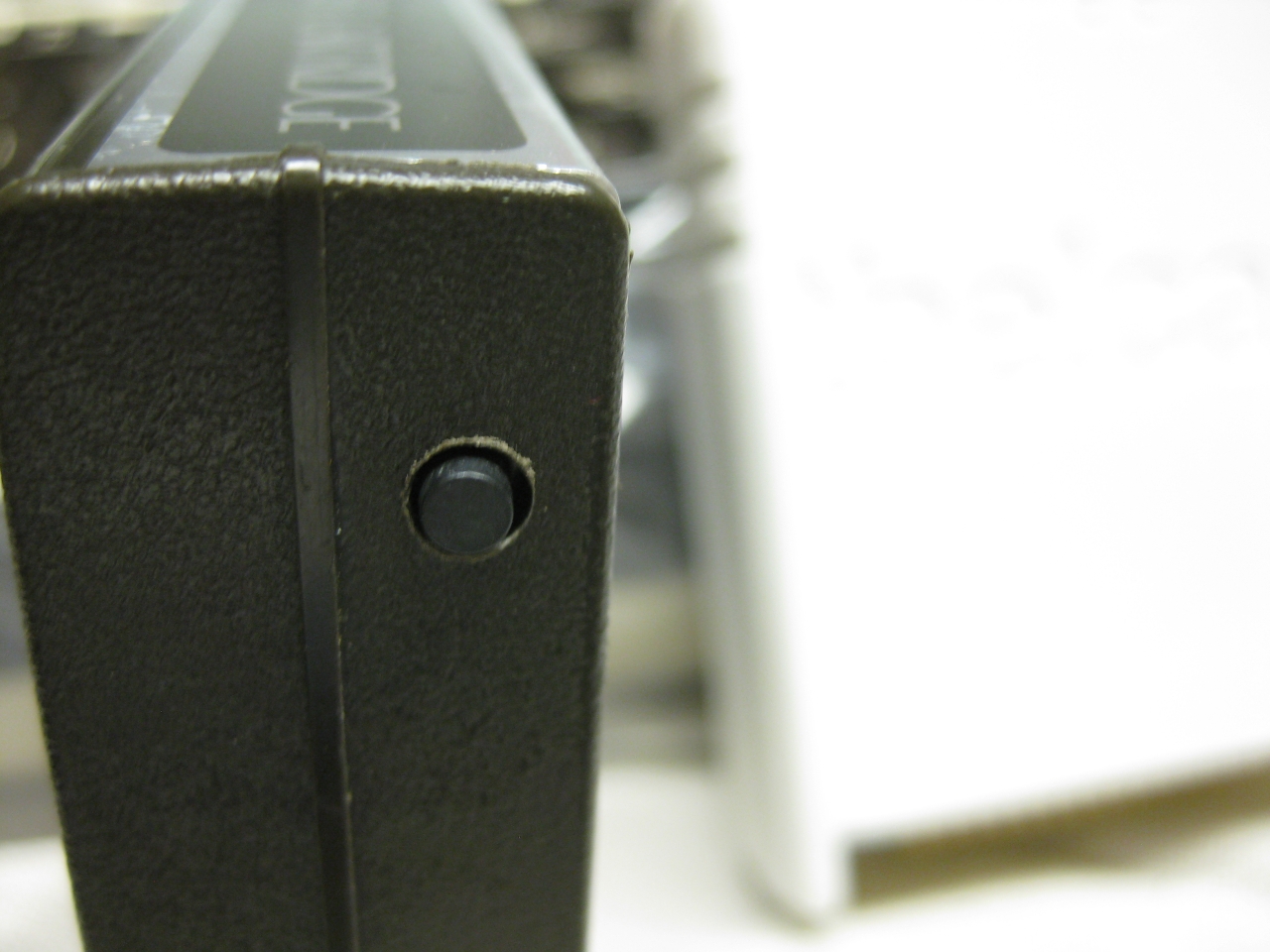
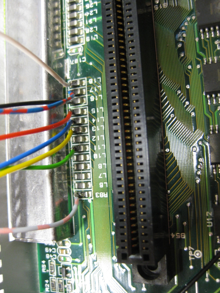
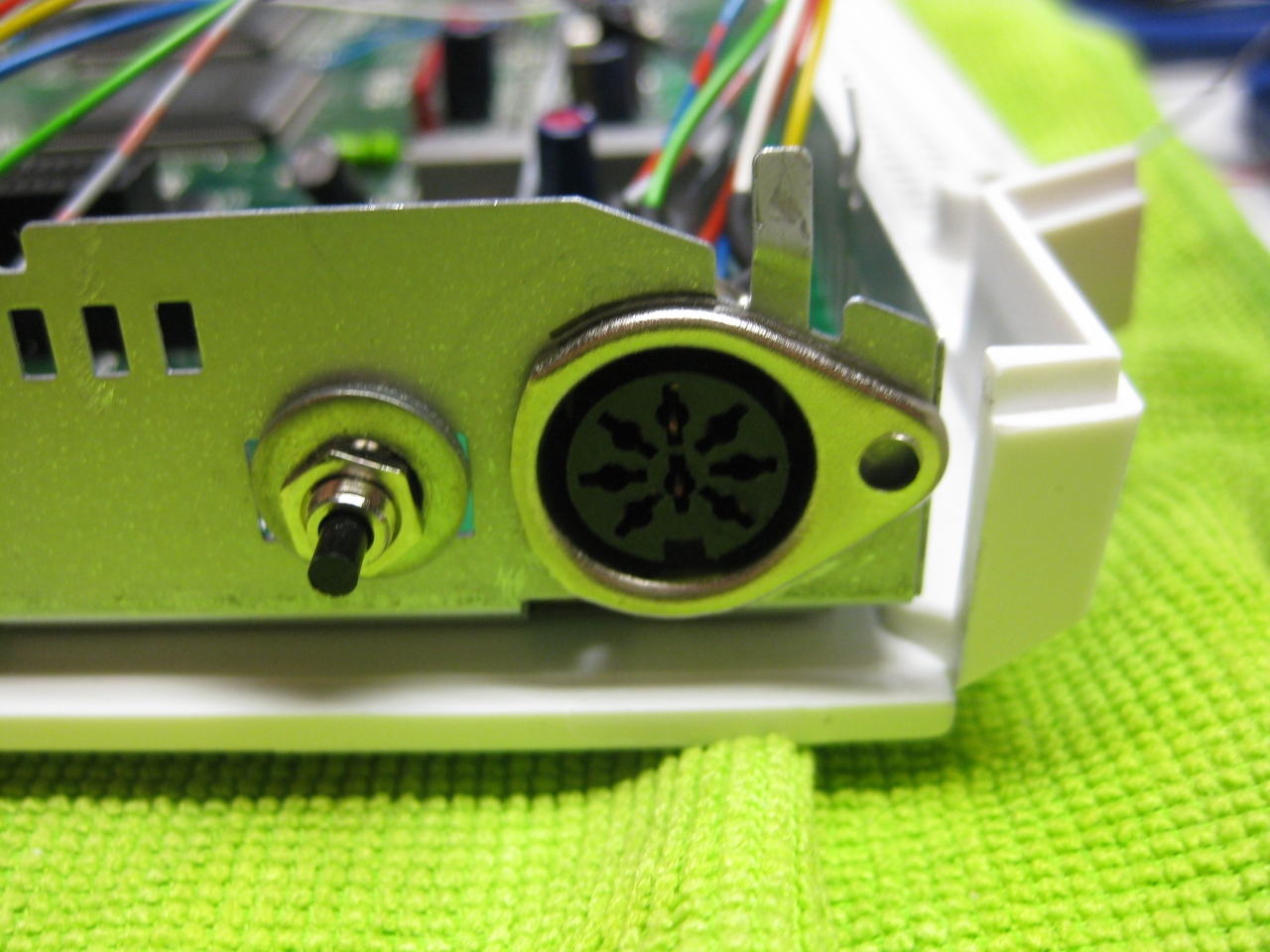
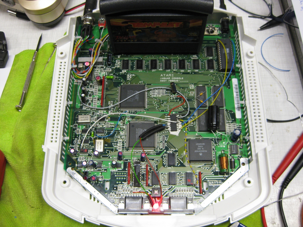
    I removed the RF-Unit to put my „standard“ DIN Connector and for adding a button instead of the chanel selector. With the help of this tiny button you can select between 50/60Hz.
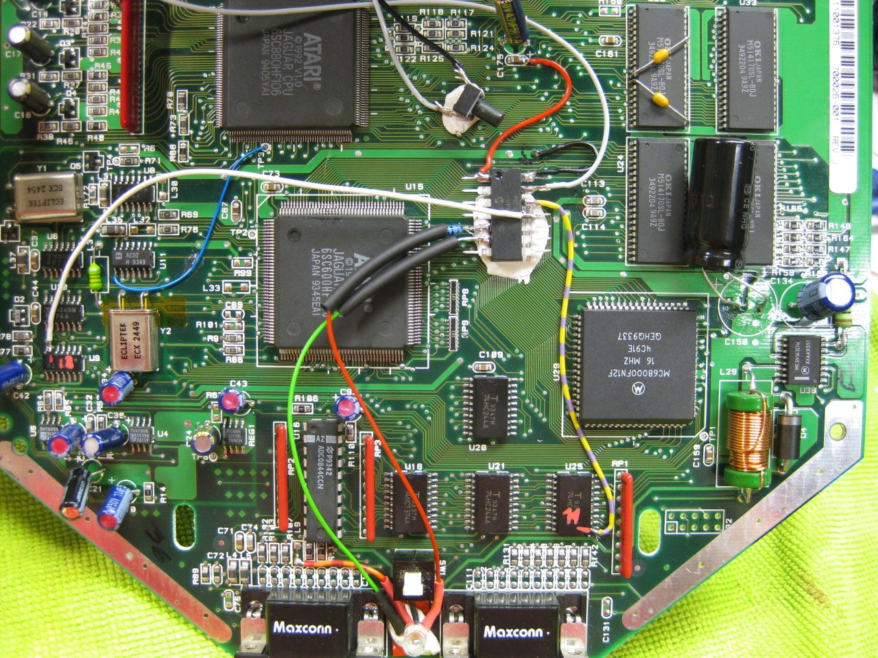
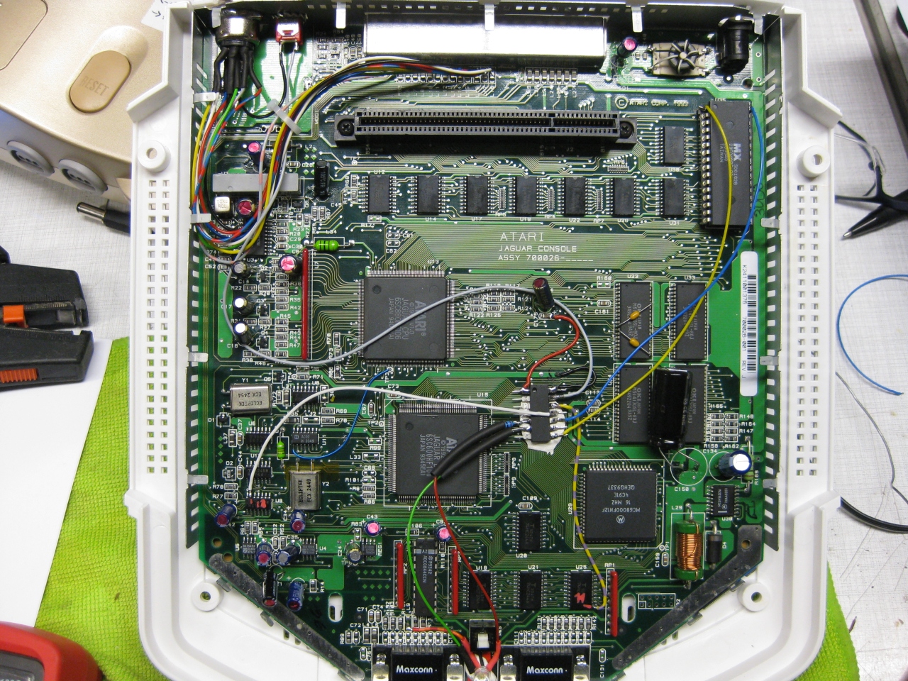


    jag_complete

    (Overview)

    jag_50_60_zoom

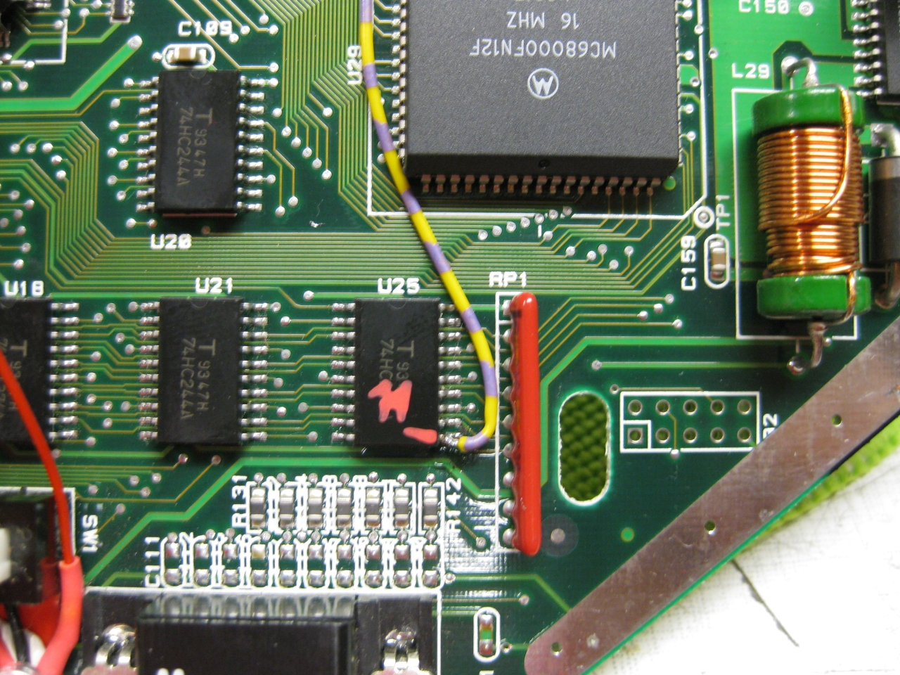
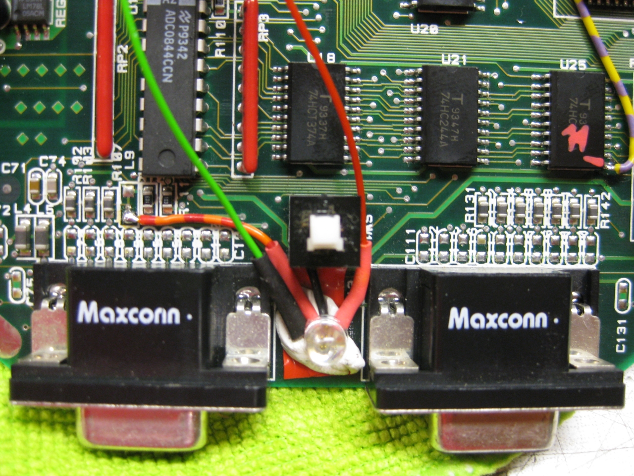
    (U25 Pin 11 sets the Console between 50 Hz (GND) and 60Hz (5V)
    I used a US 60Hz Jaguar for modding, so you have only to solder this wire to Pin 11

    Jaguar_R140_removed_60Hz
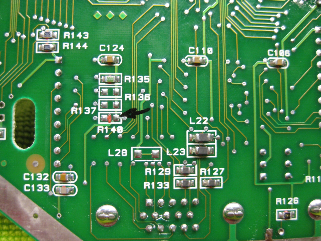
    Attention If you use the PAL console you have to look downunder and remove a Resistor R140!


    jag_reset_zoom

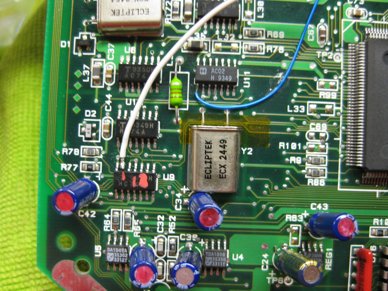
    (The Reset Line you will find U9 Pin 13  (GND = reset)


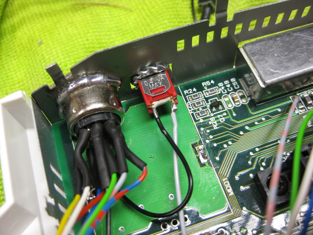
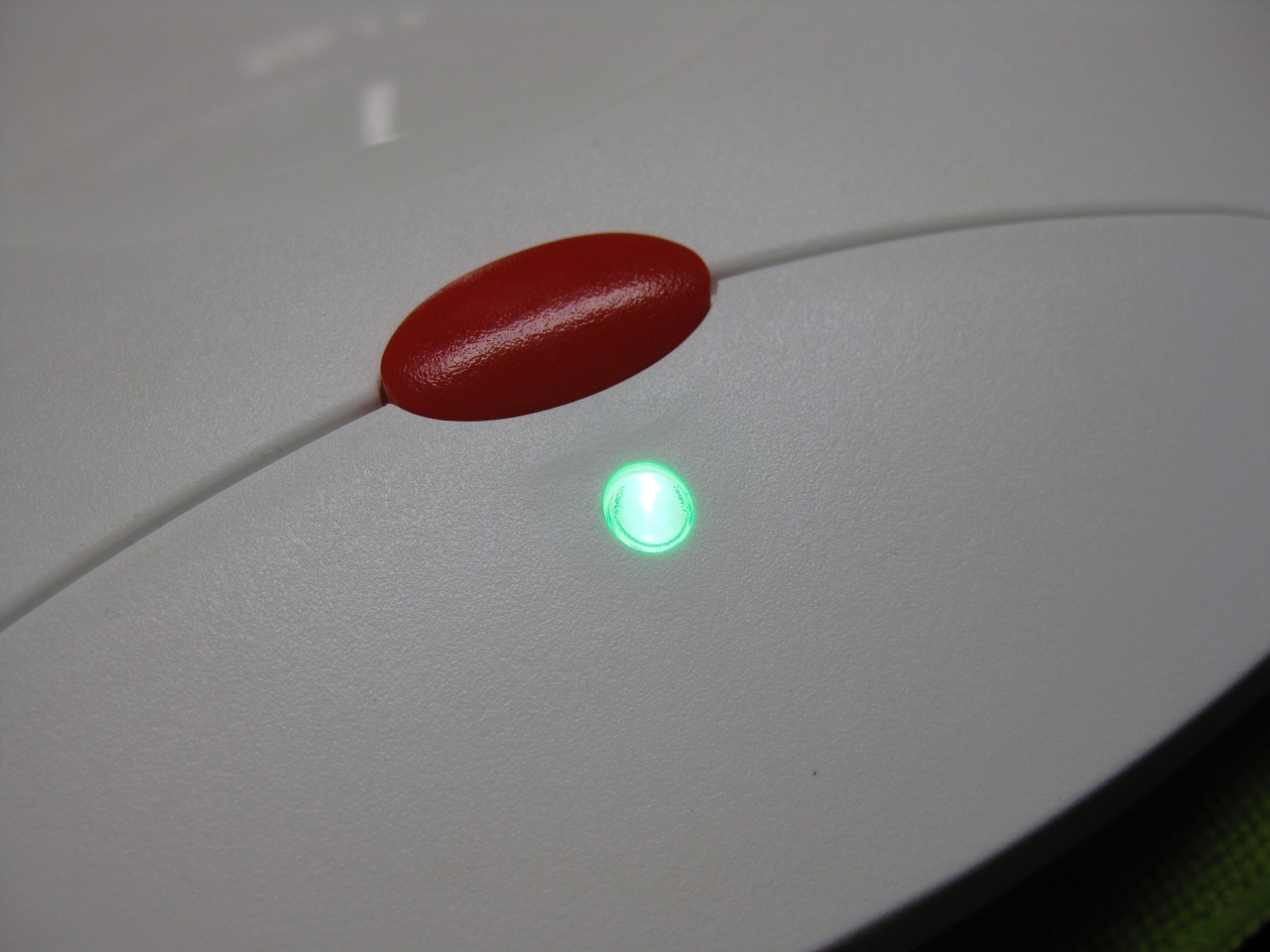
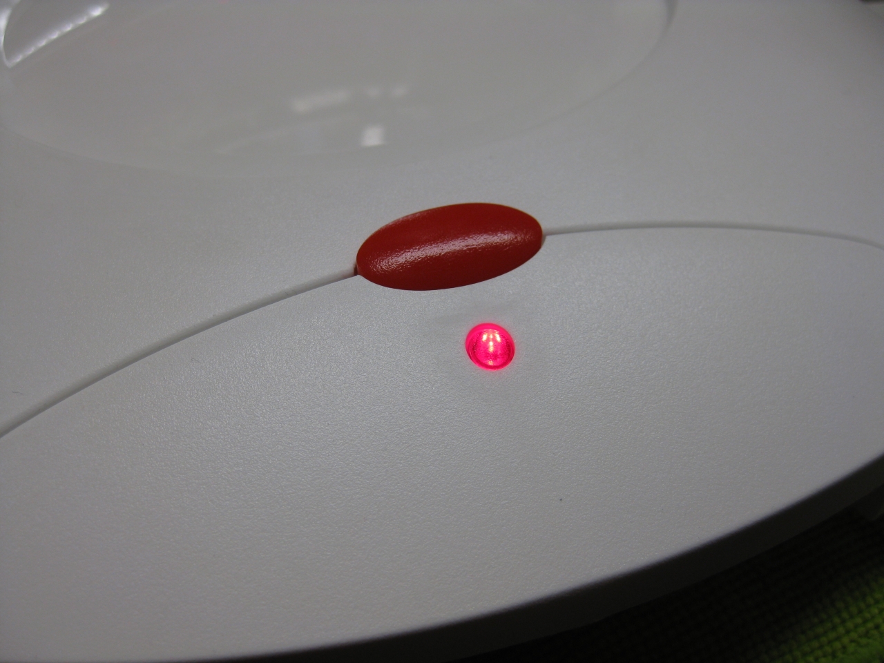
    I removed the original LED and put instead a RGB-Led.

    I set red for 60Hz and green for 50Hz.

    If you find blue better, no problemo. But red/gn are the real colors of the Jaguar used in their countrys.

    jag_rgb_led_zoom

    Usage:

    Its like the switchless Mod for the Sega Saturn.

    a) When you push the button for a moment. The Jaguar will do a reset

    b) you push and hold the button. Now the Color of the LED will toogle between green and red. When you release the button

    at red -> Jaguar Resets and starts with 60Hz
    at green -> Jaguar Resets and starts with 50Hz


    Jaguar_Din_Hole

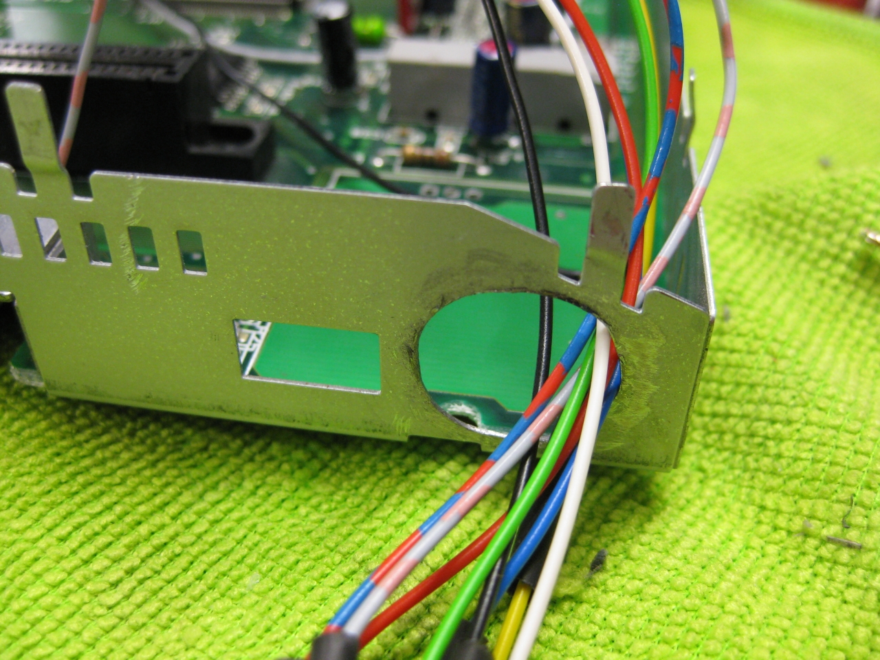
    (bigger hole for Din RGB-Connector)
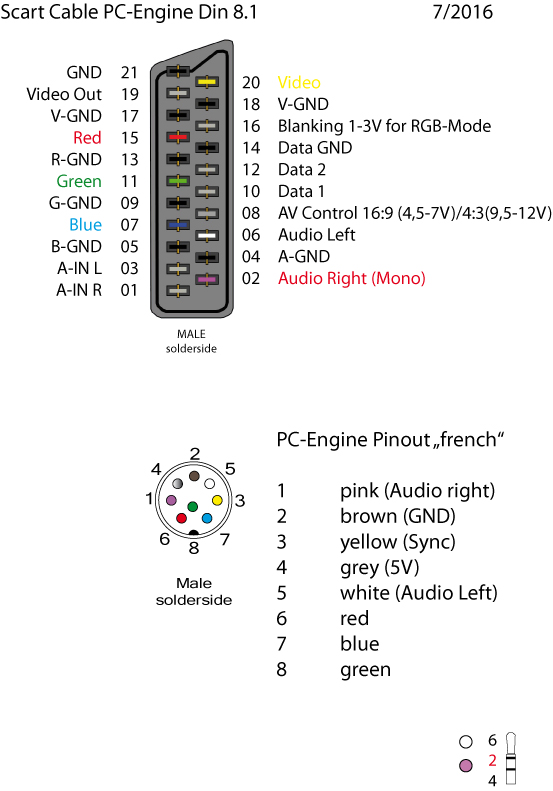
     

    Jaguar_RGB_Pinout

    (RGB-Pinout)

    Jaguar_Din_

    (Reset button)

    Jaguar_Reset_Din

    (overview)

    Jaguar_Reset_outside

    Jaguar_Final_Back

    Jaguar_Final_dental

    Jaguar_green_led

    Jaguar_red_led


    scart_PC-Engine_French_Layout_2016

    (my standard Din Pinout, based on modified 5 Pin Din PC-Engine + 3 more for RGB)


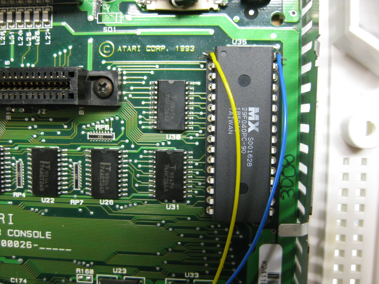
    Its time to add a 2nd Bios to the Jaguar.

    You have to remove the original Jaguar Bios and use a DIP 32 socket.

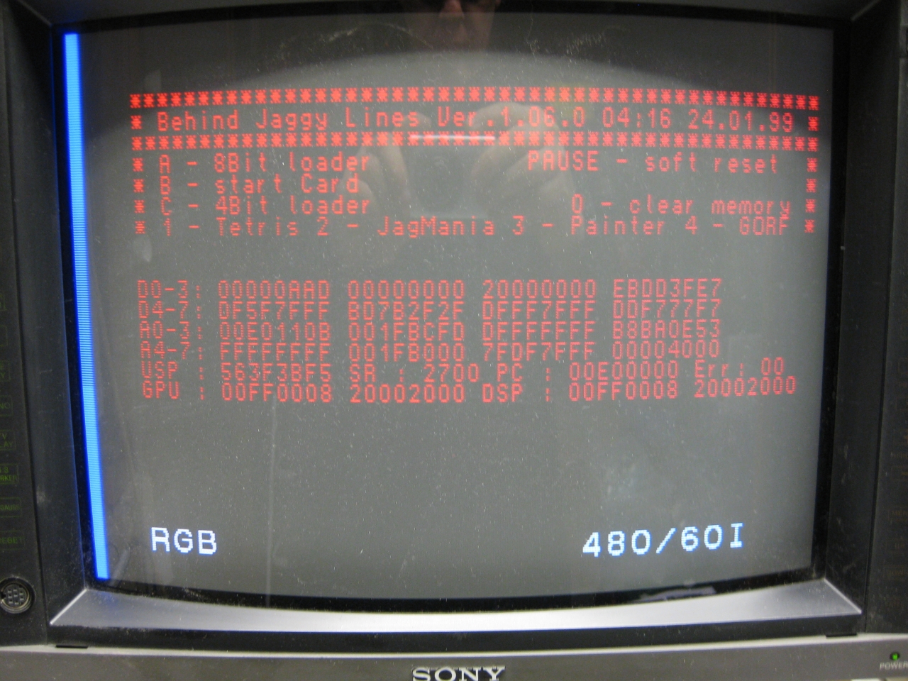
    With the help of a 29f040 FlashRom I added jagbios and BJL1.06

    You need to concat the bios files:
    Use: windows command: copy /B jagbios.bin + jagbios.bin + jagbios.bin + BJL106.bin 4in1bios.bin

    and burn 4in1bios.bin to the 29F040 FlashRom
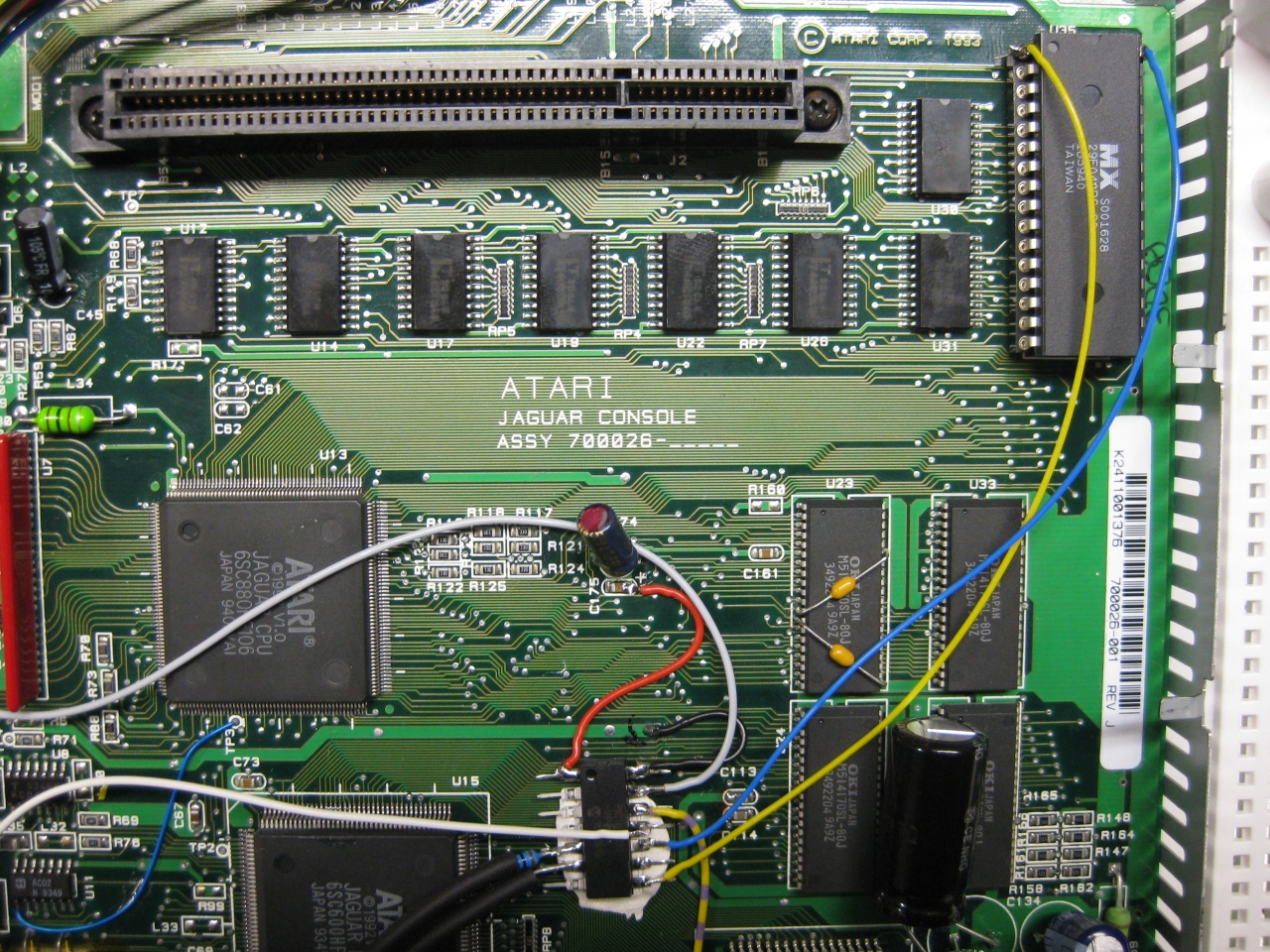
     

    29f040_zoom


    29f040_wiring_


    jaguar_complete

    (overview)

    jag_complete_green_bjlbios

    jag_bjl_bootscreen

    jaguar_red_complete

    jaguar_jag_rom

    Update 23.6.2017

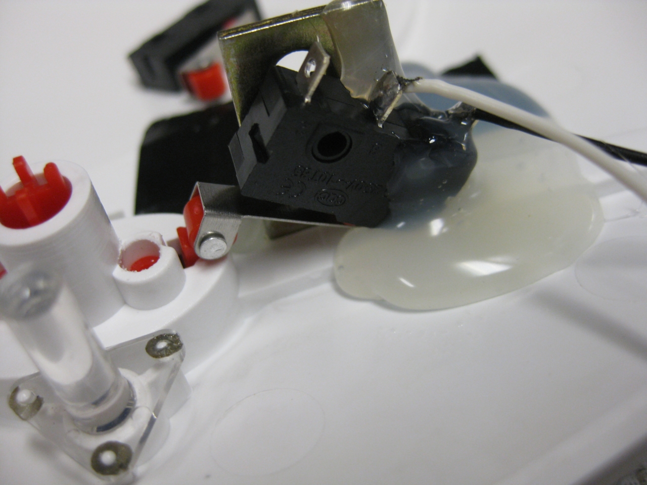
    I put a switch beneath the Power Switch to make it like a „real switchless“ mod.

    So the Power switch can pressed a litte to:

    • change 50/60
    • Reset
    • switch between original Bios and BJL

    OR

    Press it more deep to Power Off and Power ON like normal

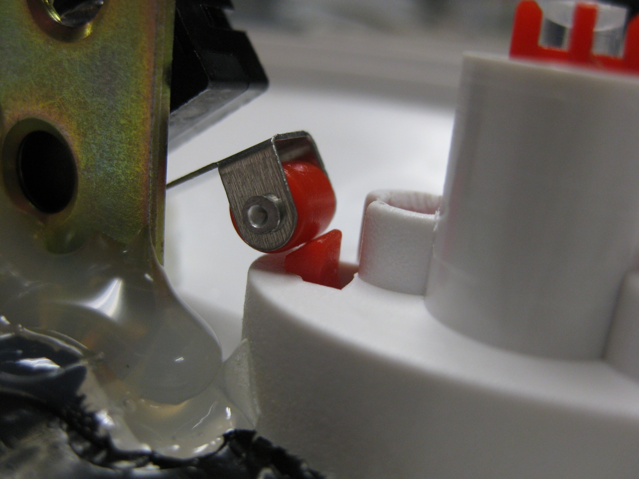
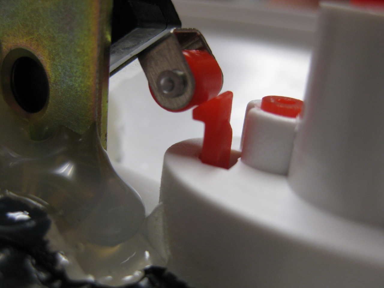
    I used a little switch with a ball at the end and put it inside like this:

    jag_switchless_1

    standard

    jag_switchless_3

    with button pressed a „little“

    jag_switchless_4


    Youtube Video

    (Sorry about wrong JBL speaking its BJL Loader 😉

  • Atari 2600 gets internal UWRC wireless Receiver

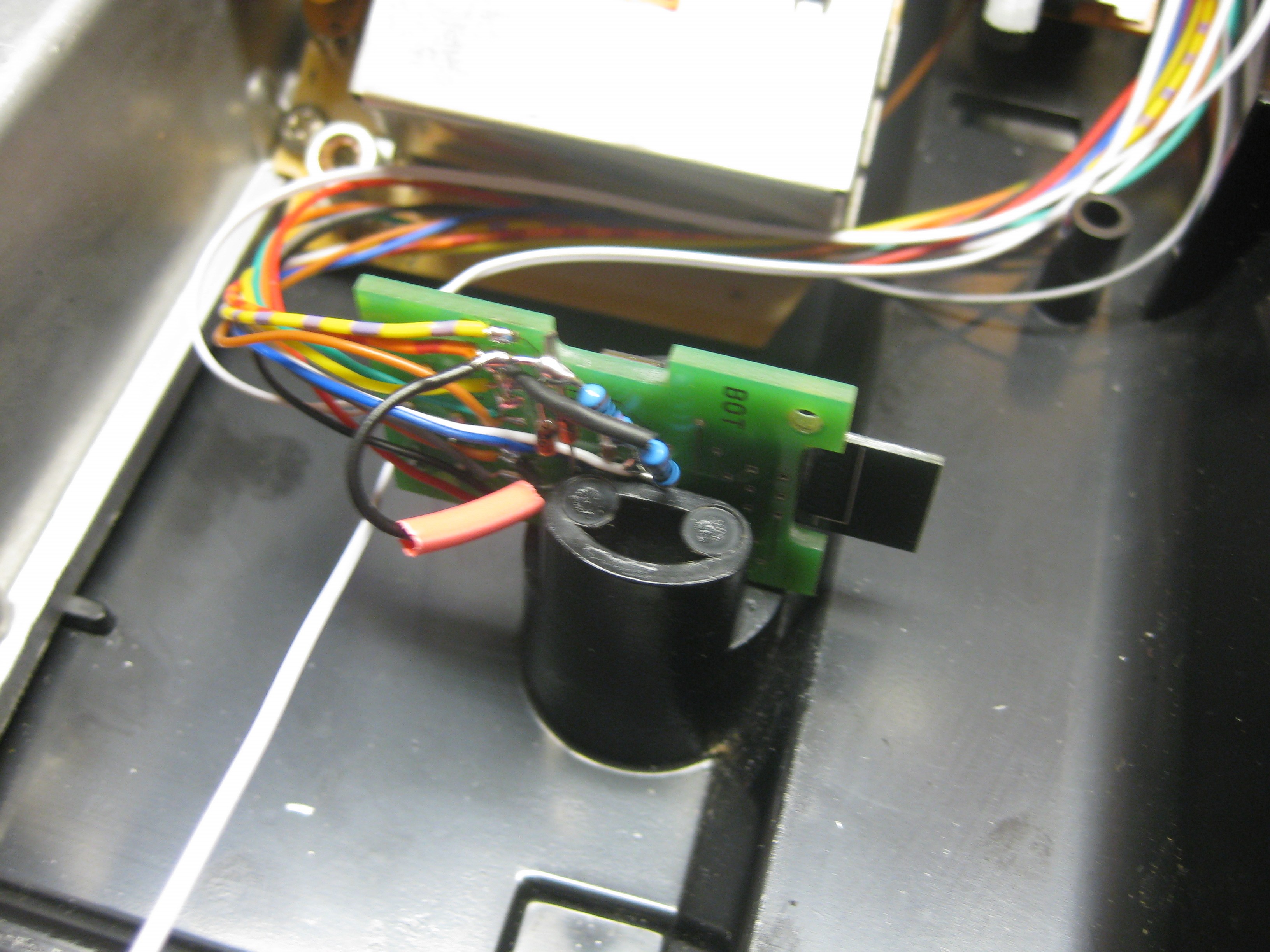
    I used a old revision (rev1) of micros neogeo Receiver and put it inside of the A2600 6 swich.

    I was modified before with A2600RGB from tim worthington and I used some more switches like select, reset from the Atari and extra button from tim worthingstons 2600RGB PCB
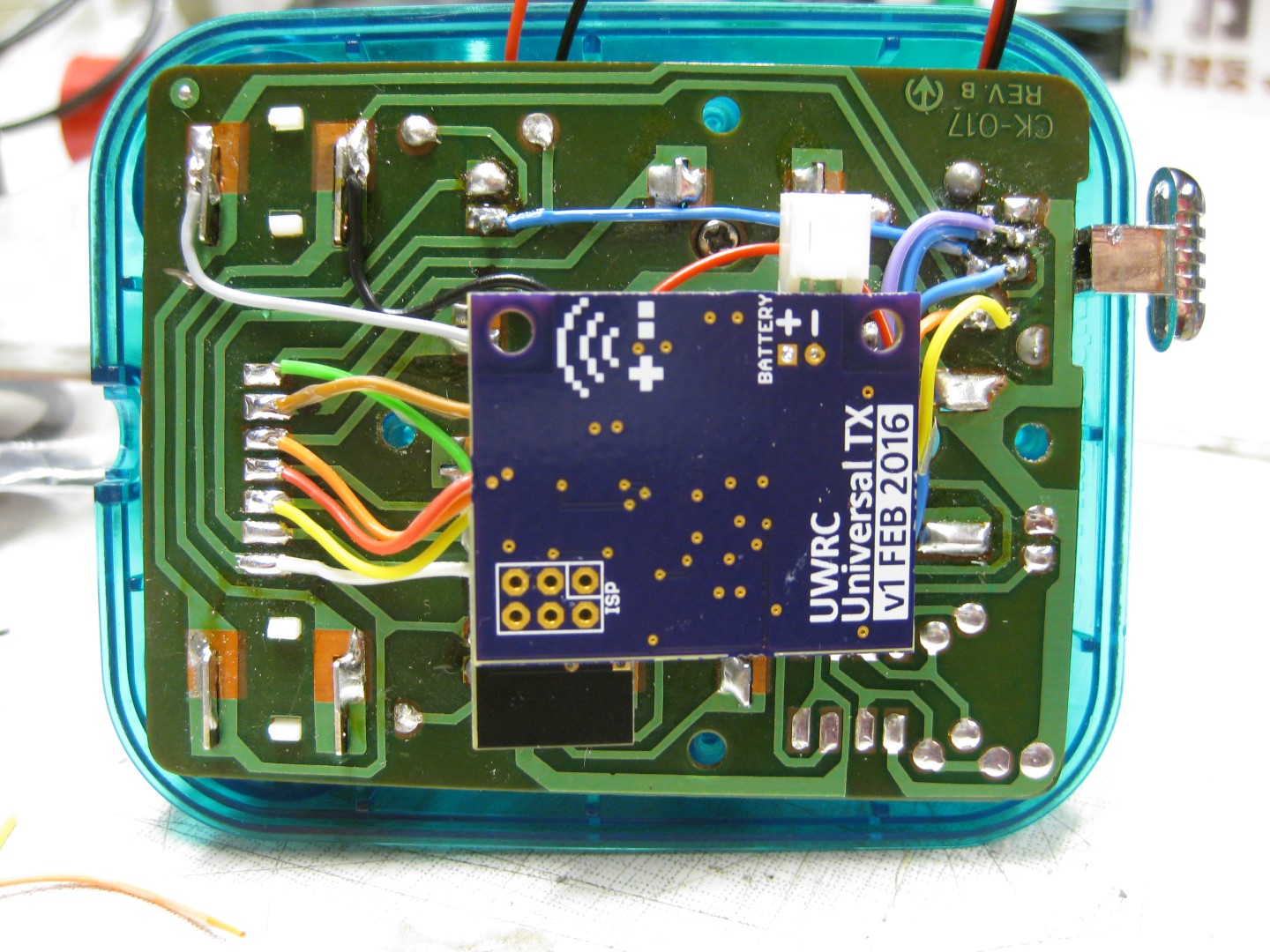
    UWRC

    Button A = normal FireButton 1 of Atari (Pin 6)

    Button B = Firebutton 2 (Pin 9)

    Select  =    Extra Button A2600RGB PCB

    Start  = Start of Atari 2600

    Button C= Select of Atari 2600

    Button D = Palette switch A2600RGB PCB


    All normal Controllers will work after mod too. Like paddle, racing, joystick.


    IMG_8941

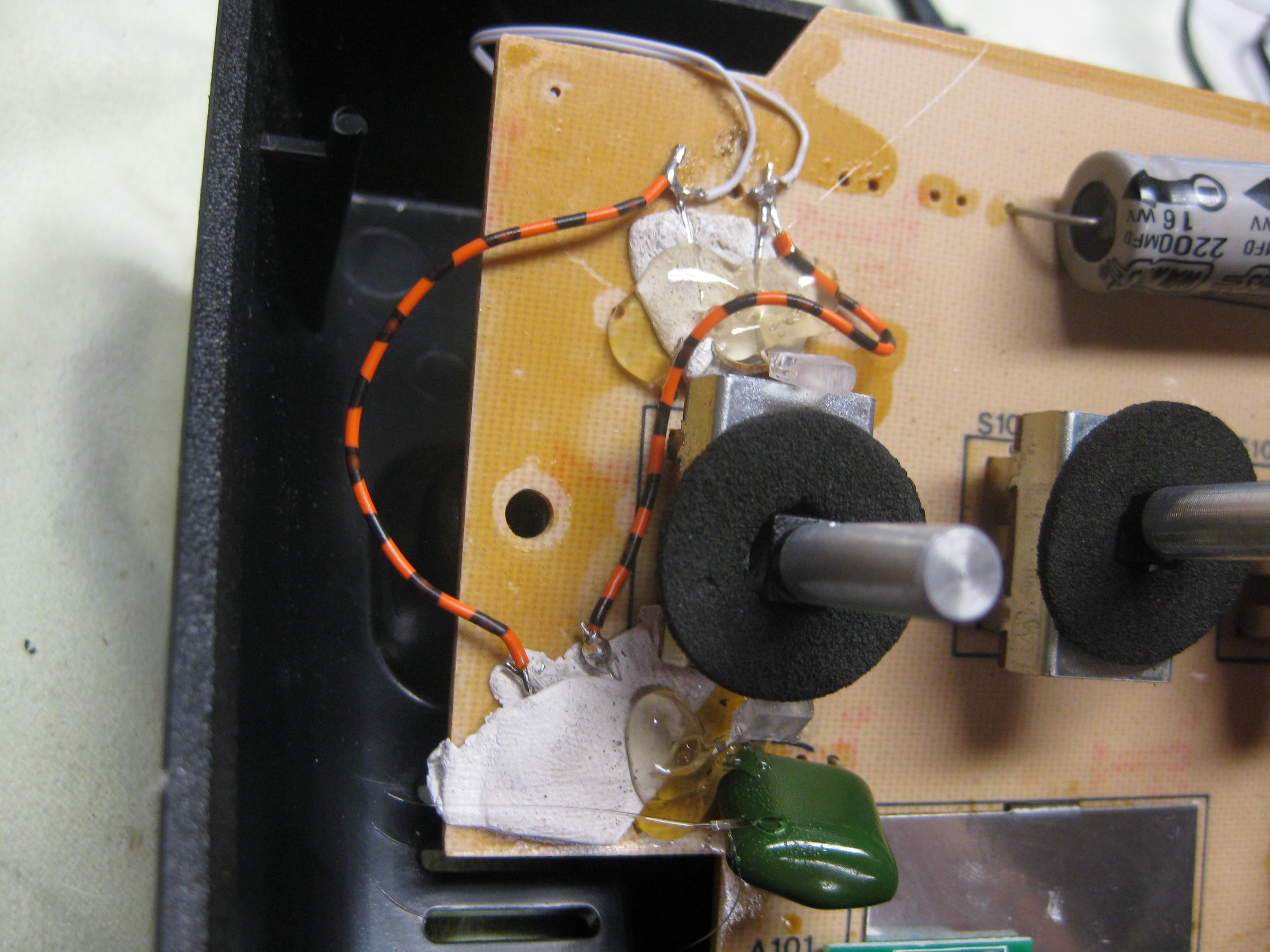
    (diodes, needed to make special functions from A2600RGB working, R=10k as pullup)

    IMG_8944


    IMG_8950

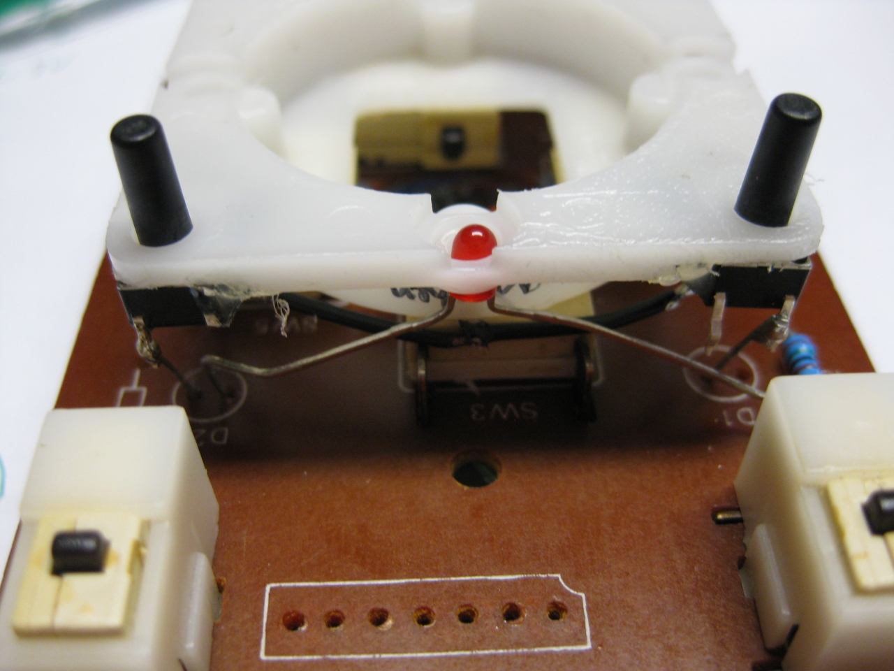
    RX Led to show it though the power switch hole upperside red led down side gn led


  • UWRC vs remote control yesterday

    here you can see the grandpa of remote control 😉

    a little comparsion between yesterdays remote and state of the art :-)))

    uwrc_yesterday_vs_today (7)uwrc_yesterday_vs_today (6)uwrc_yesterday_vs_today (5)uwrc_yesterday_vs_today (4)uwrc_yesterday_vs_today (3)uwrc_yesterday_vs_today (2)uwrc_yesterday_vs_today (1)

  • UWRC Competition Pro Mini

    I bought some Competition Pro Mini and most of them have brocken microswitches 🙁

    I found some replacements here:

    http://www.voelkner.de/products/43525/Microschalter-Ultraminiatur-5A-250V-Sim.-R.-Hebel.html

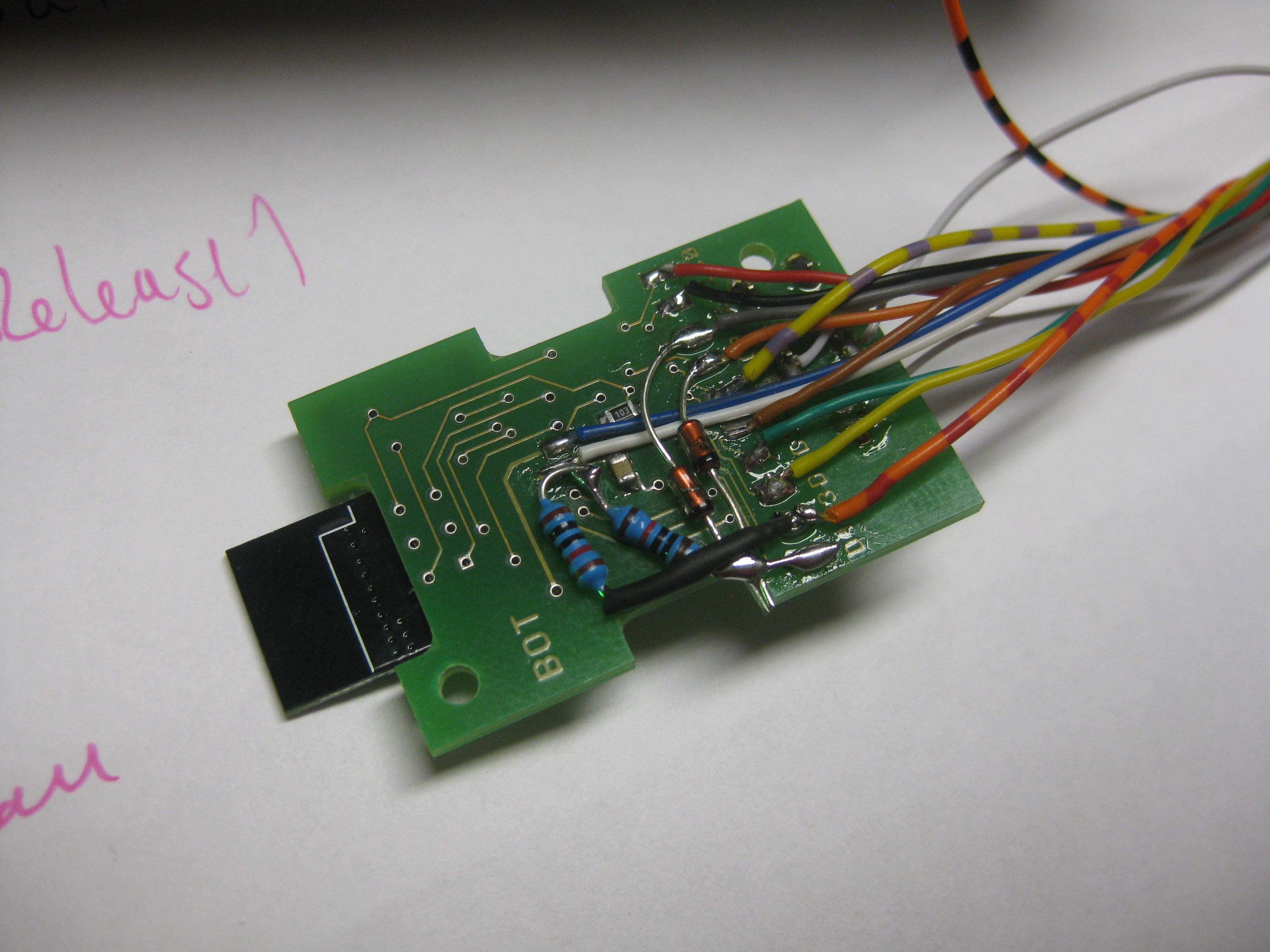
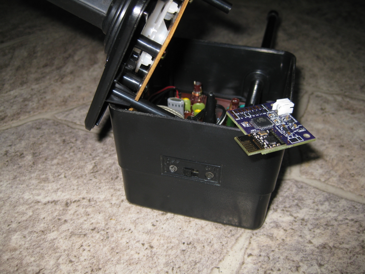
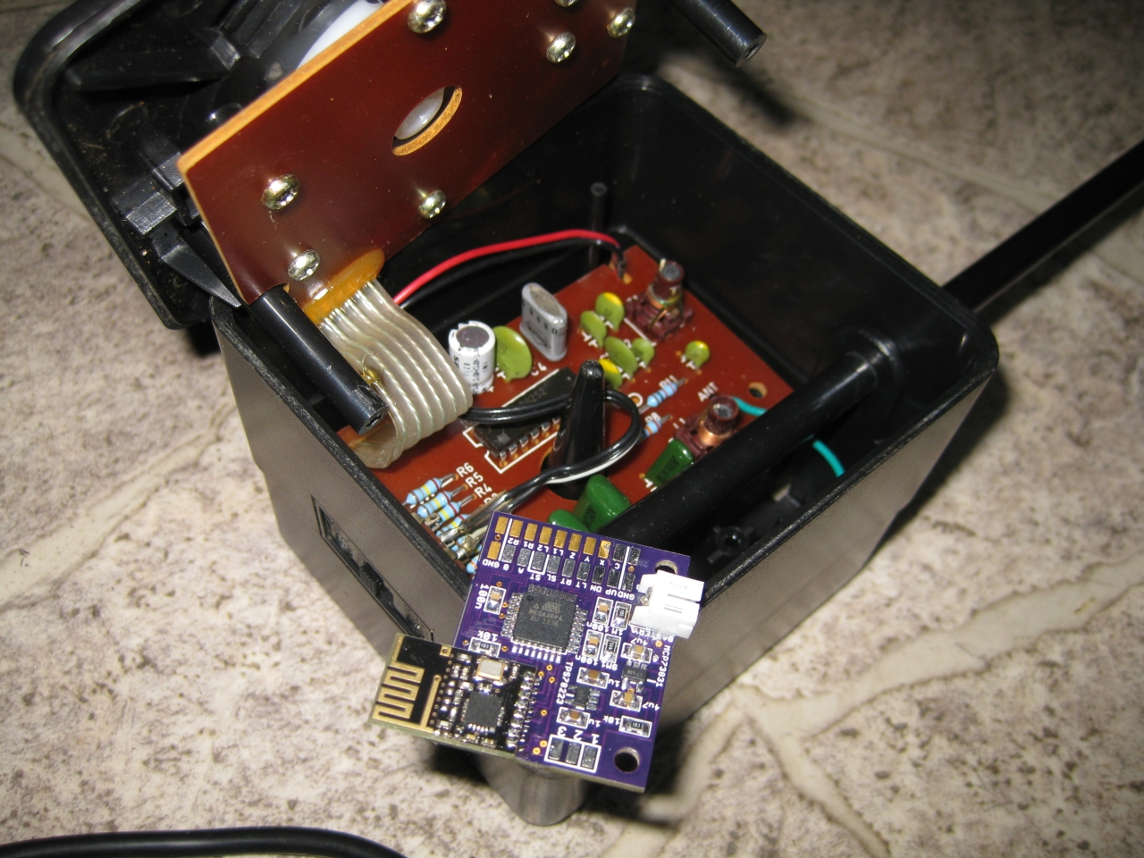
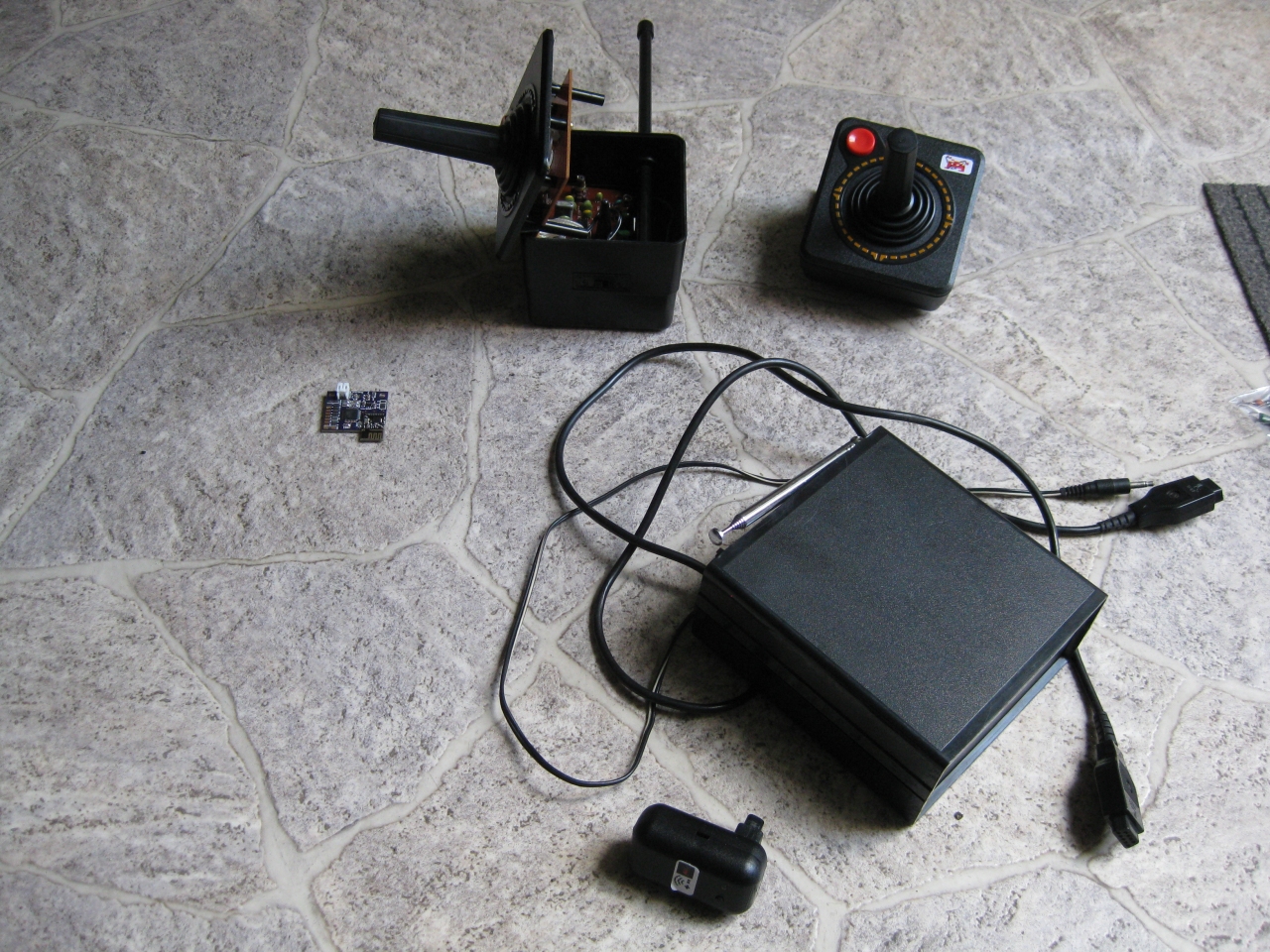
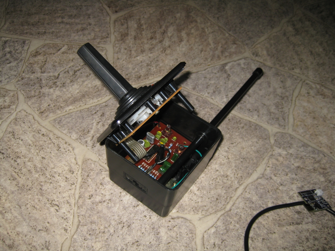
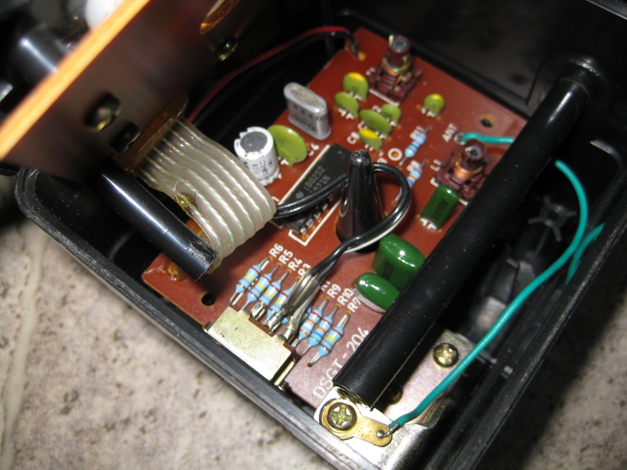
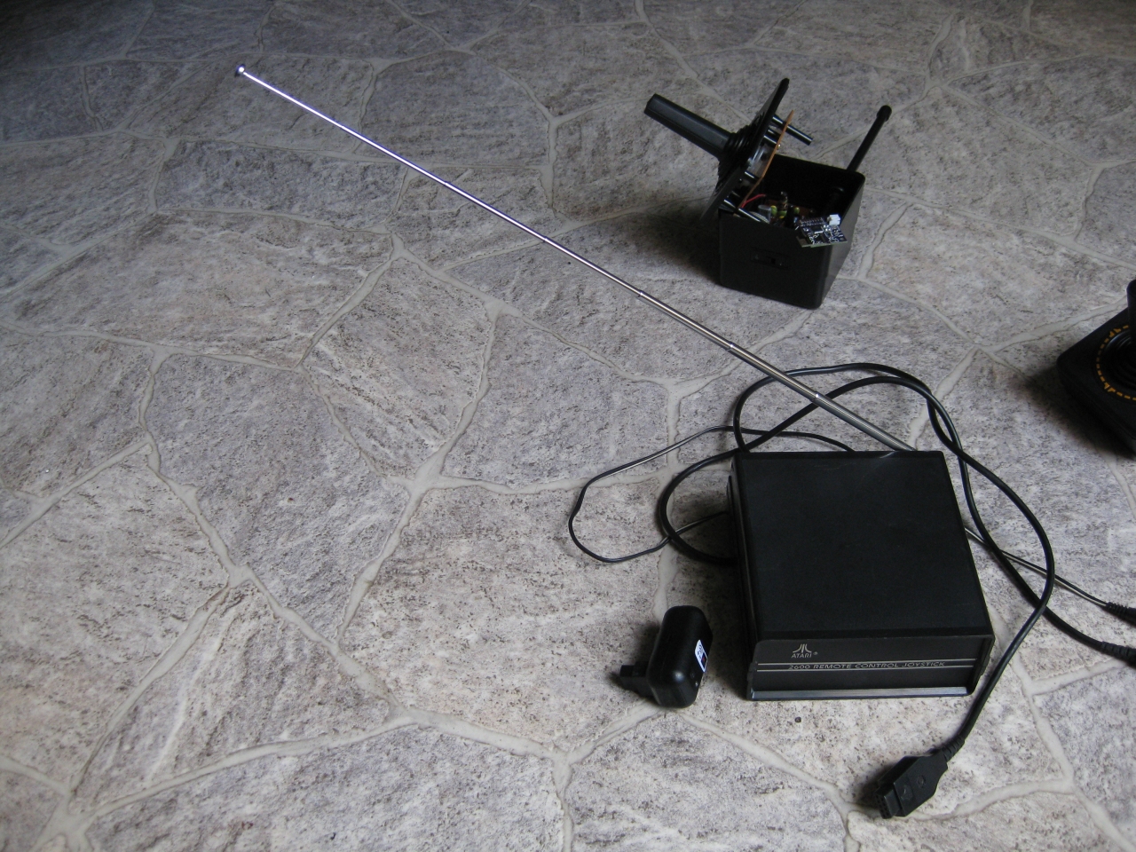
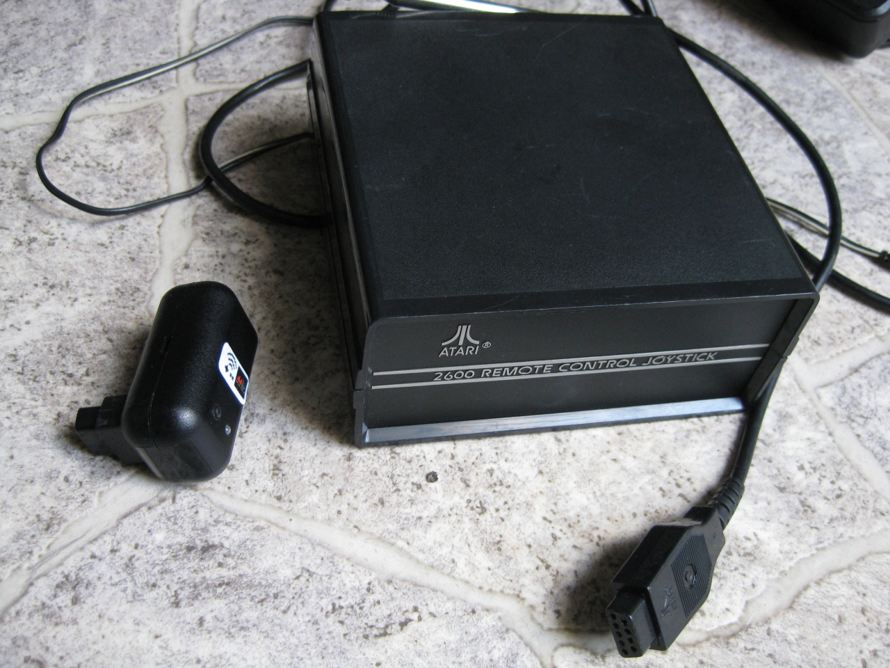
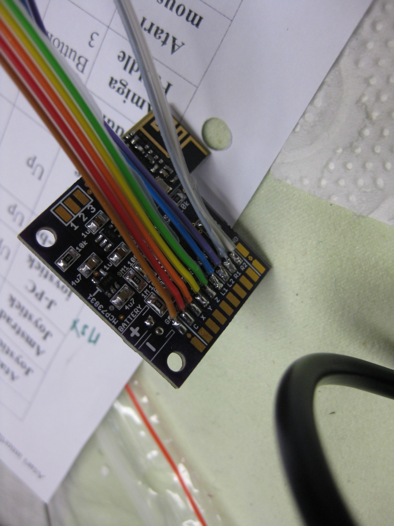
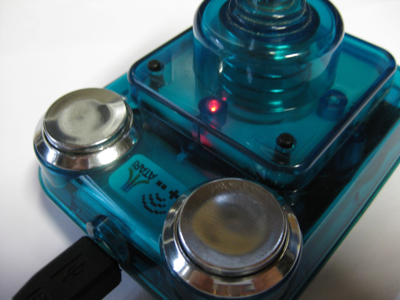
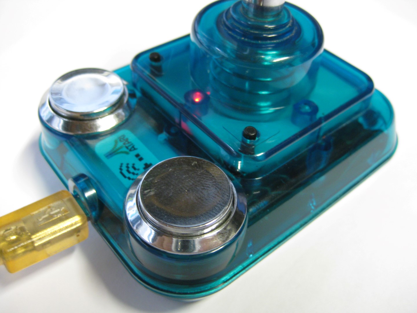
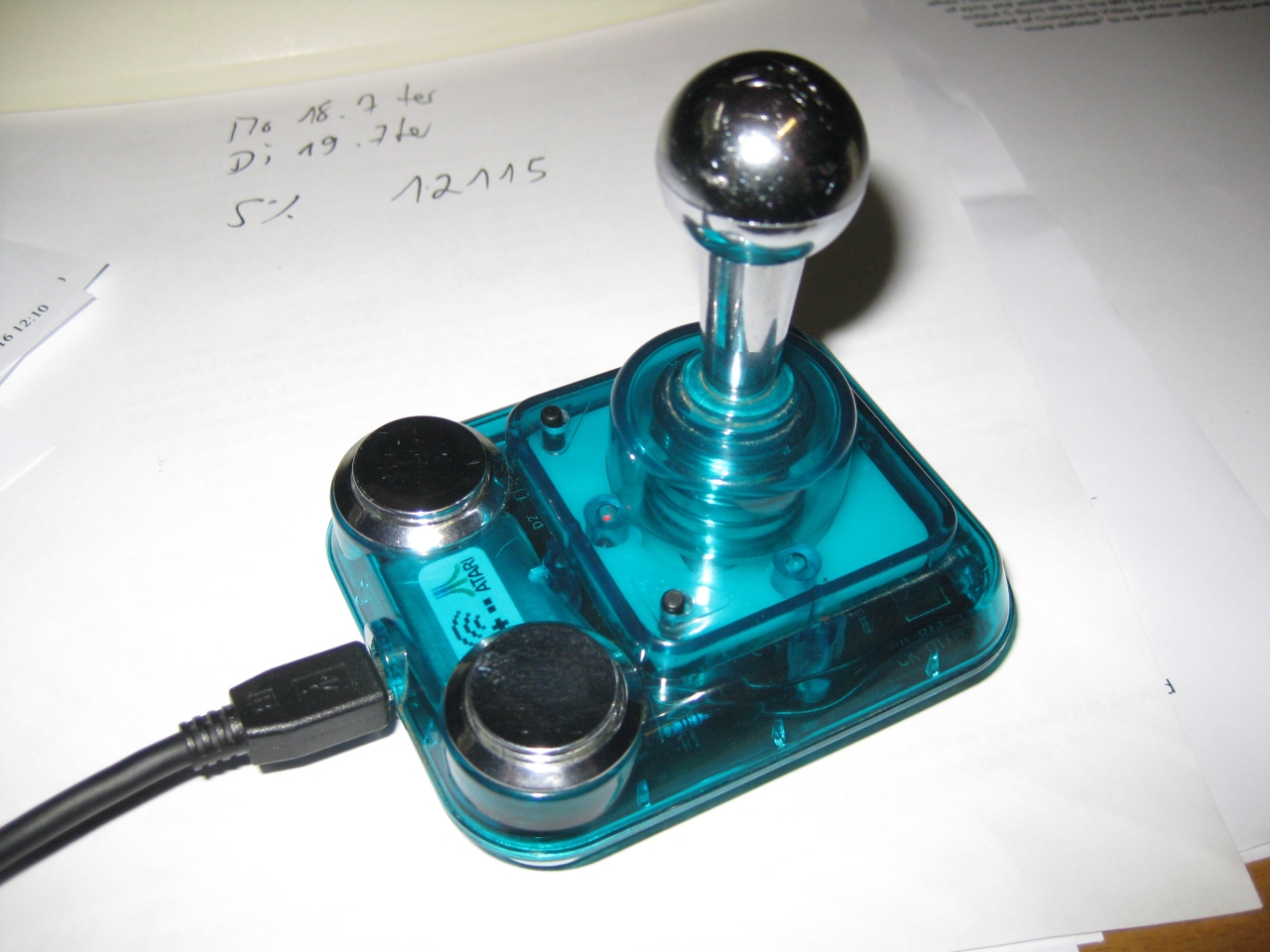
    It was very tricky to add the Universal TX PCB in this tiny stick but after all it looks great 🙂
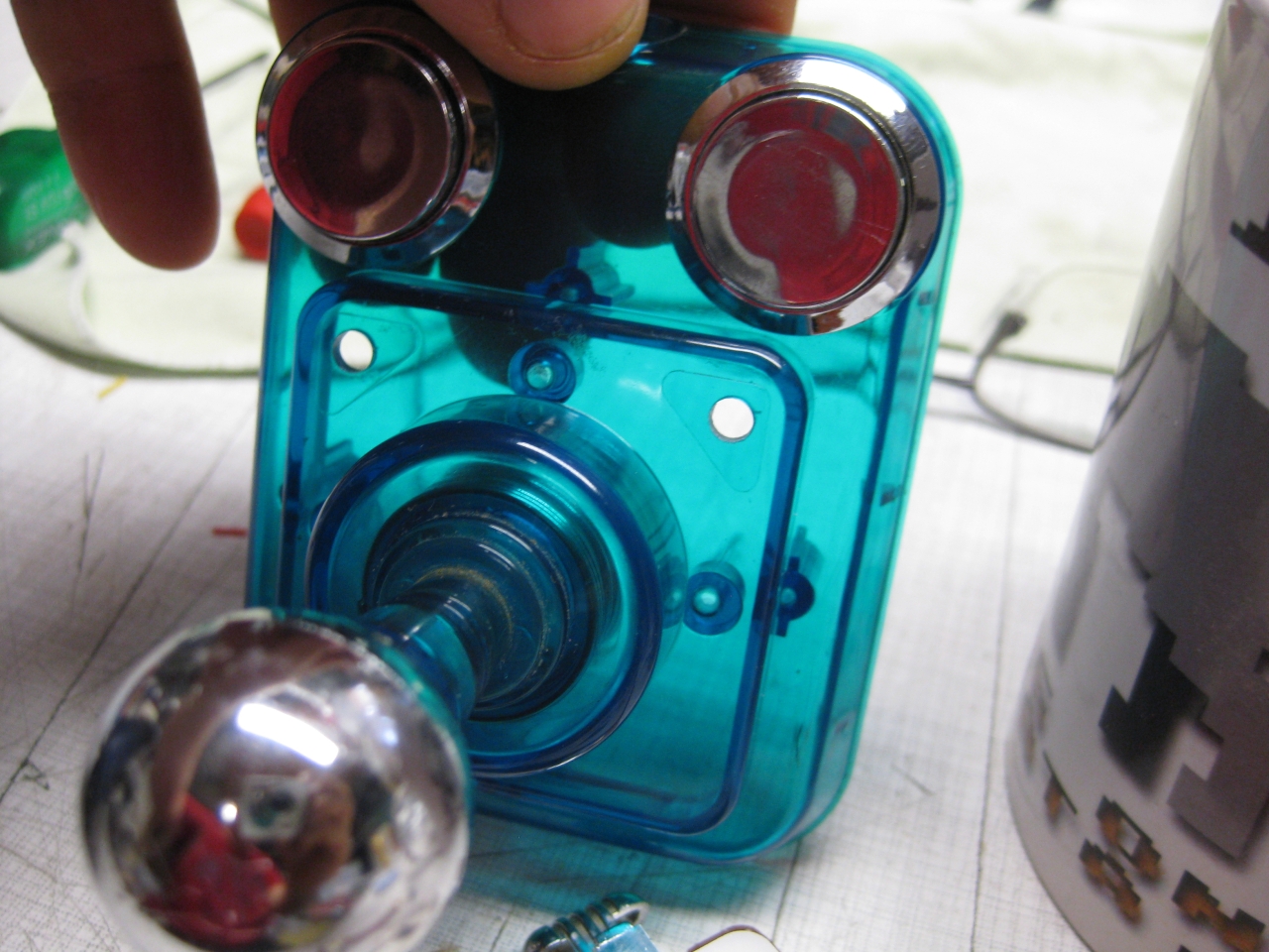
    After removing original parts I add a Led and two more micro switches for Select and Start.

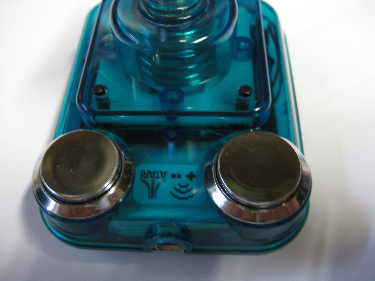
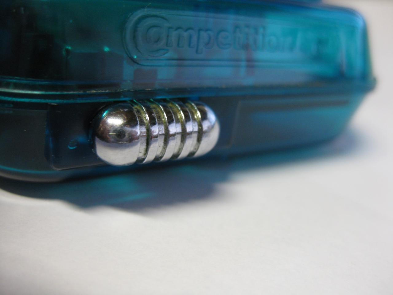
    The chrome switch to swap between Layout Select/Start and Button X, Button Y

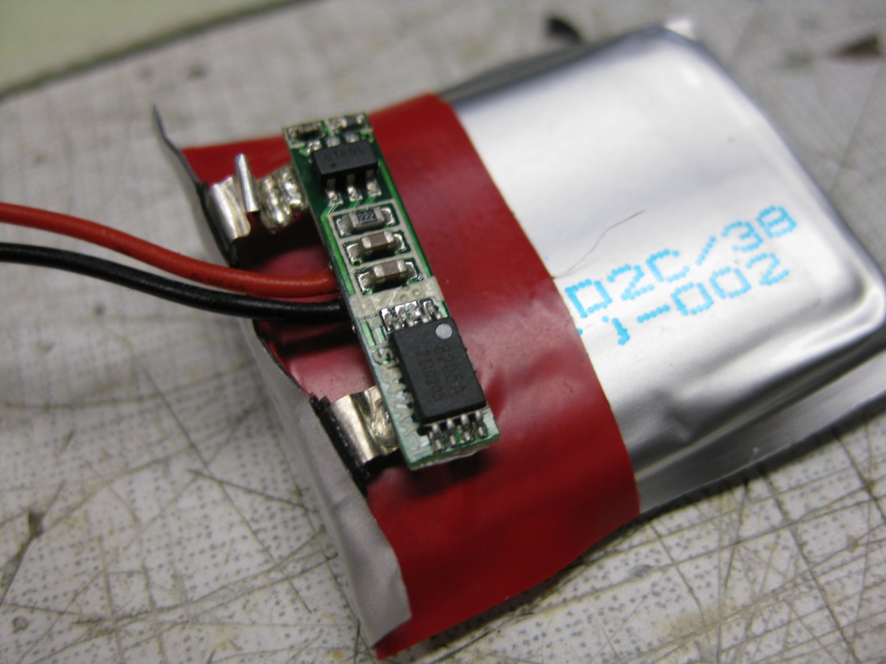
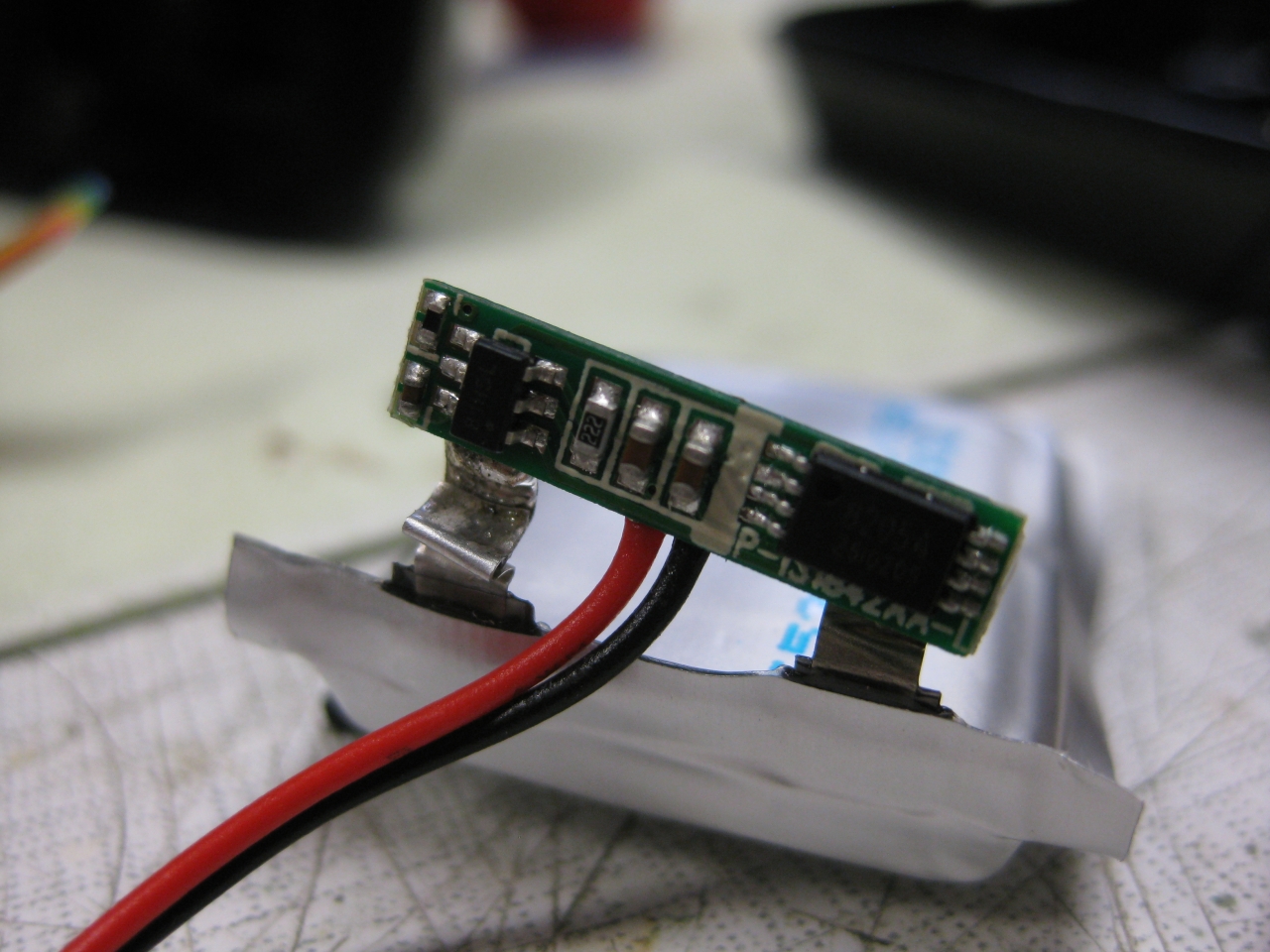
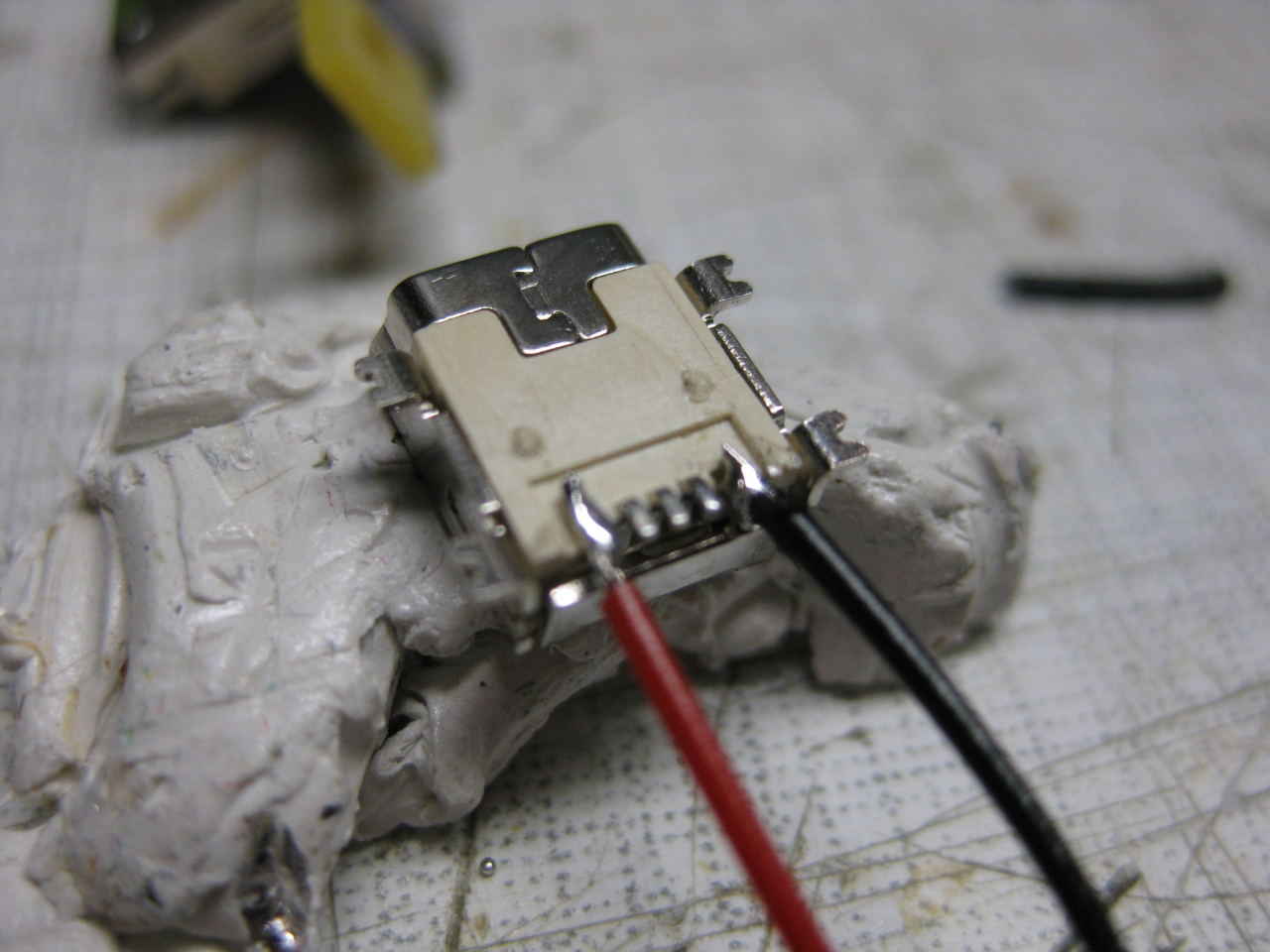
    I must move the electronic of the LiPo to put it between the two fire Buttons

    IMG_8039 IMG_8038

    uwrc_tx_1 mini_1 IMG_8537 IMG_8541 (Large) IMG_8550 IMG_8547 IMG_8559 (Large) IMG_8566

    IMG_8534 IMG_8544