Kategorie: NEC

  • Ultimate PC Engine Super Grafx

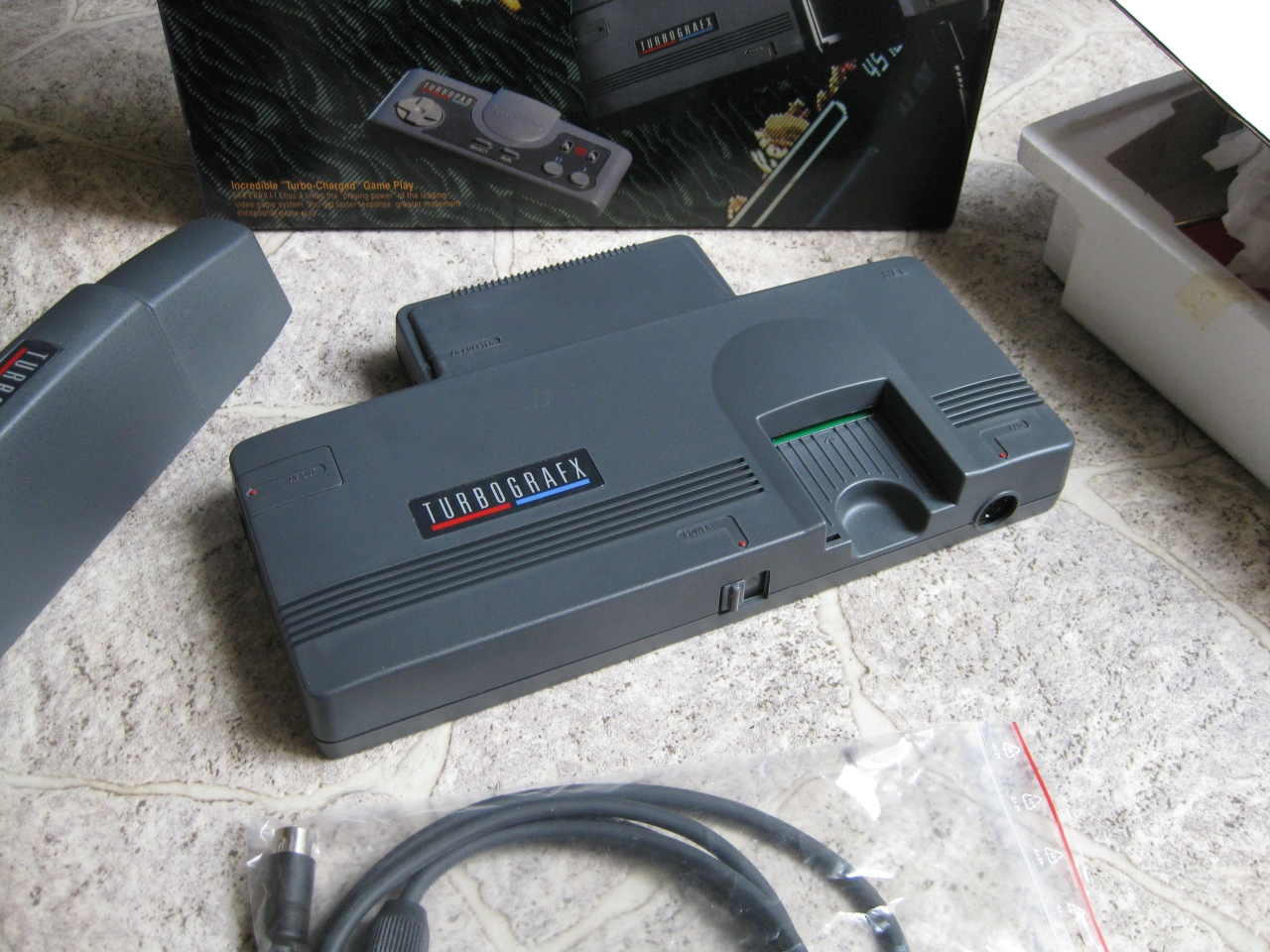
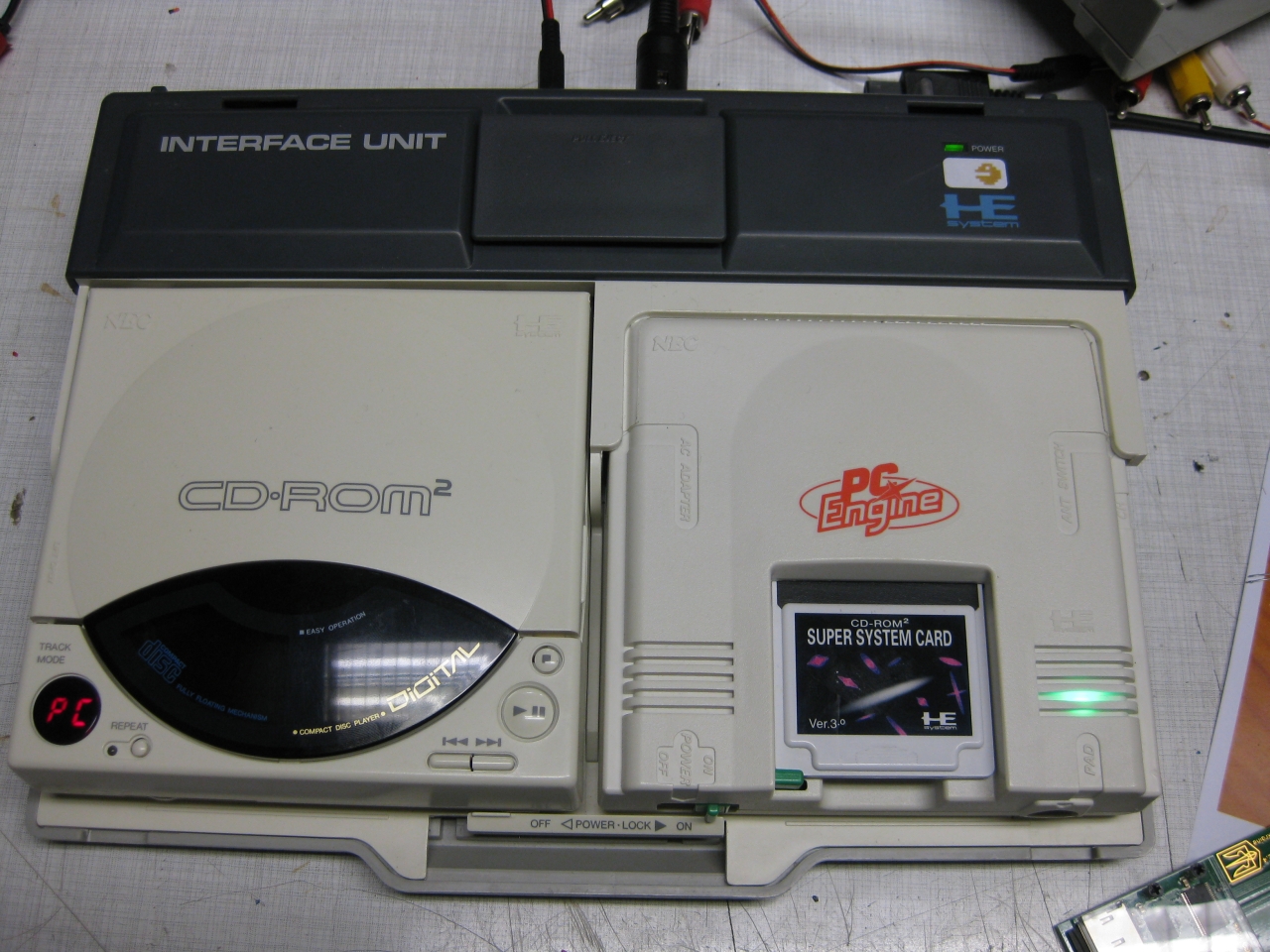
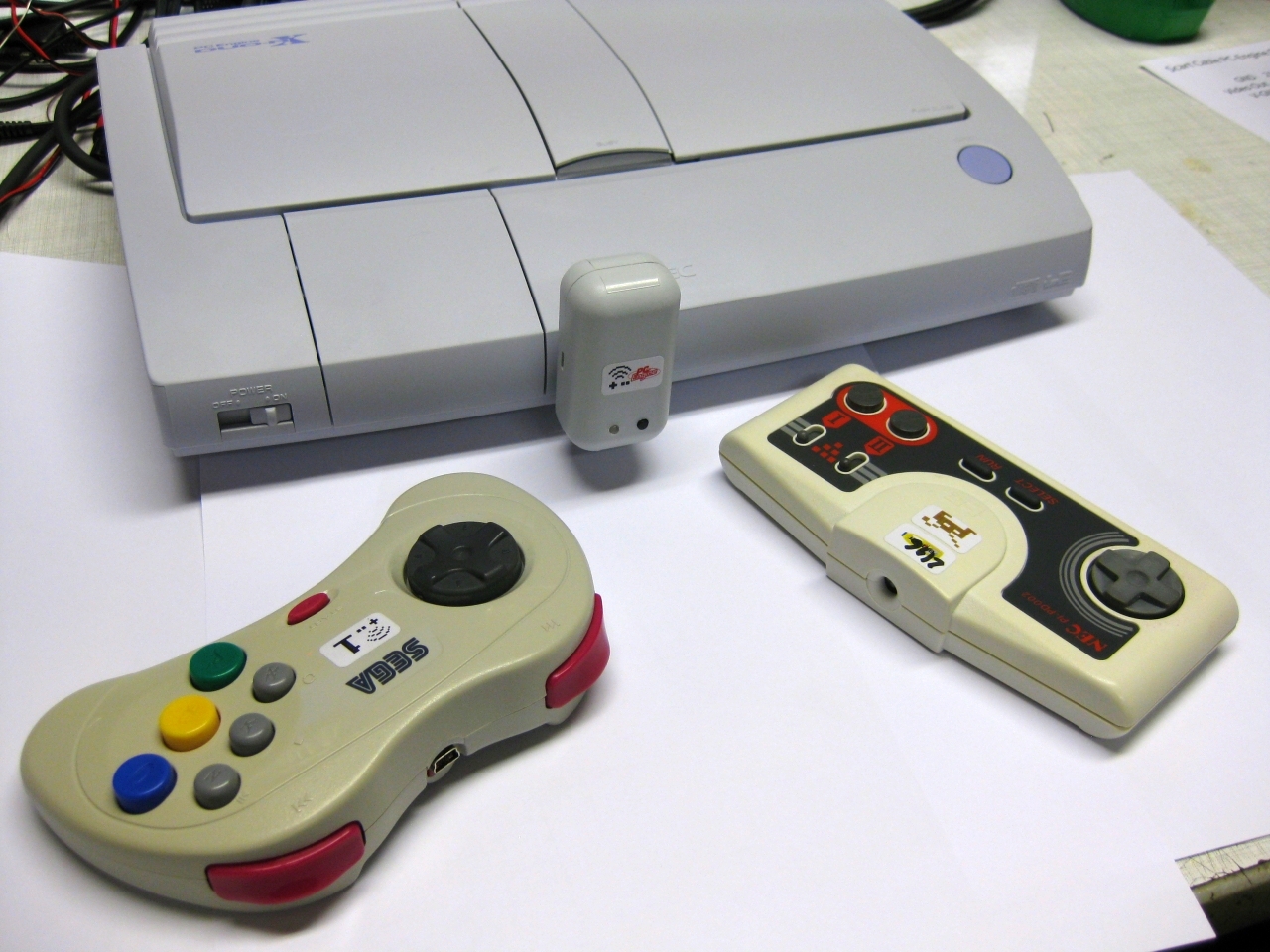
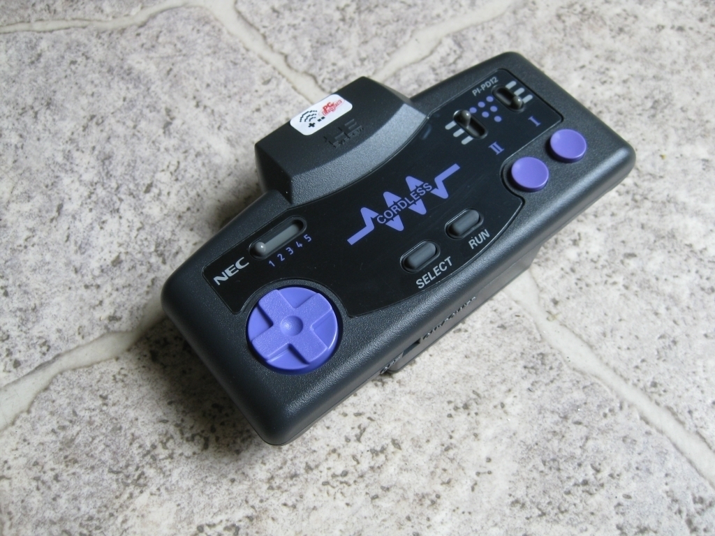
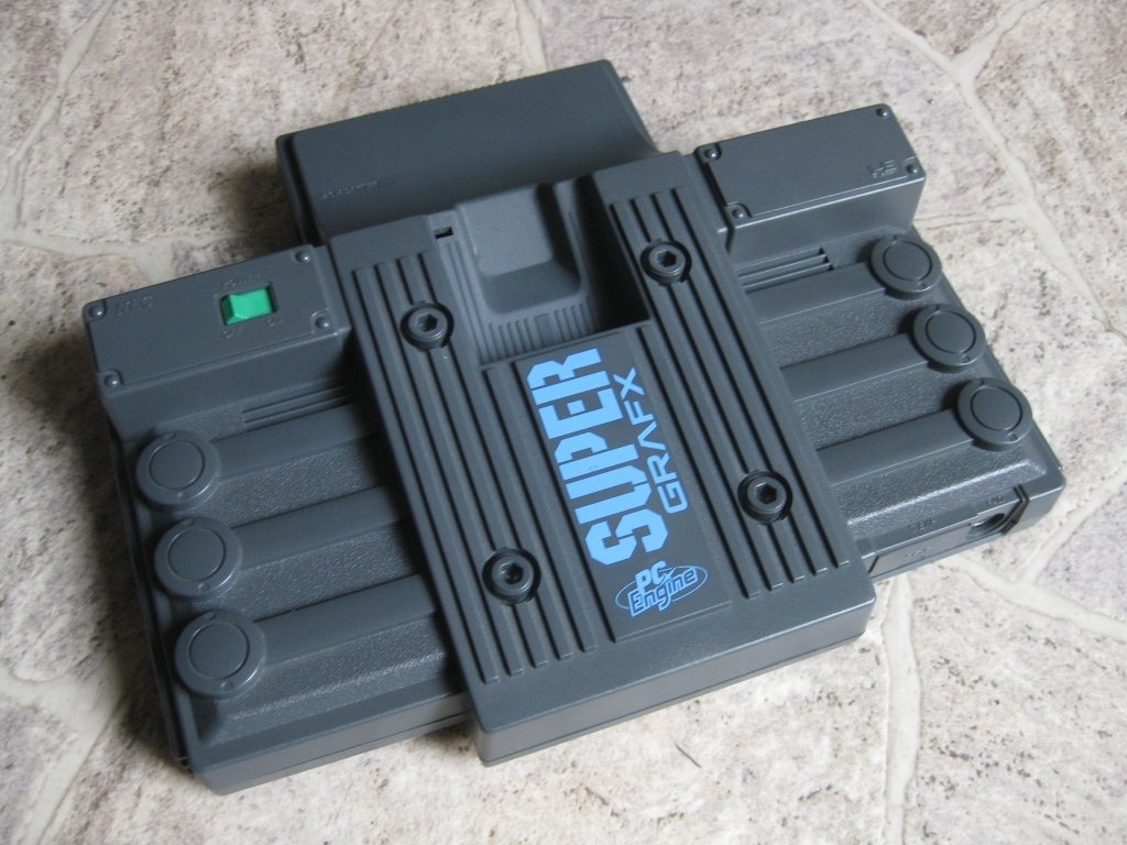
    One to rule them all. Flagship of the PC-Engine Fleet -The Supergrafx.
    A customer asked me if I can put a SSDS3 inside a Super Grafx and I loved the idea 🙂

    SuperGrafx2
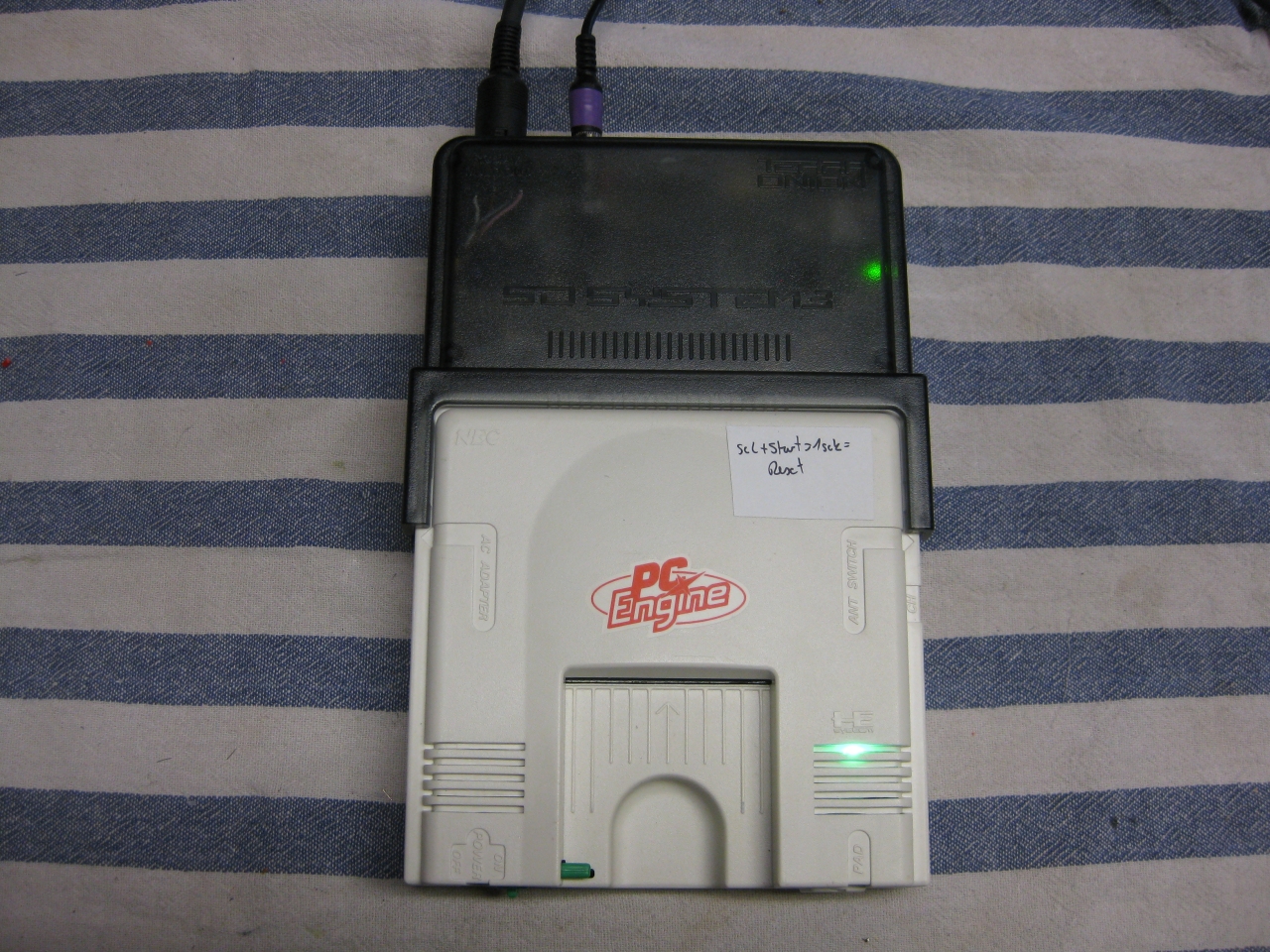
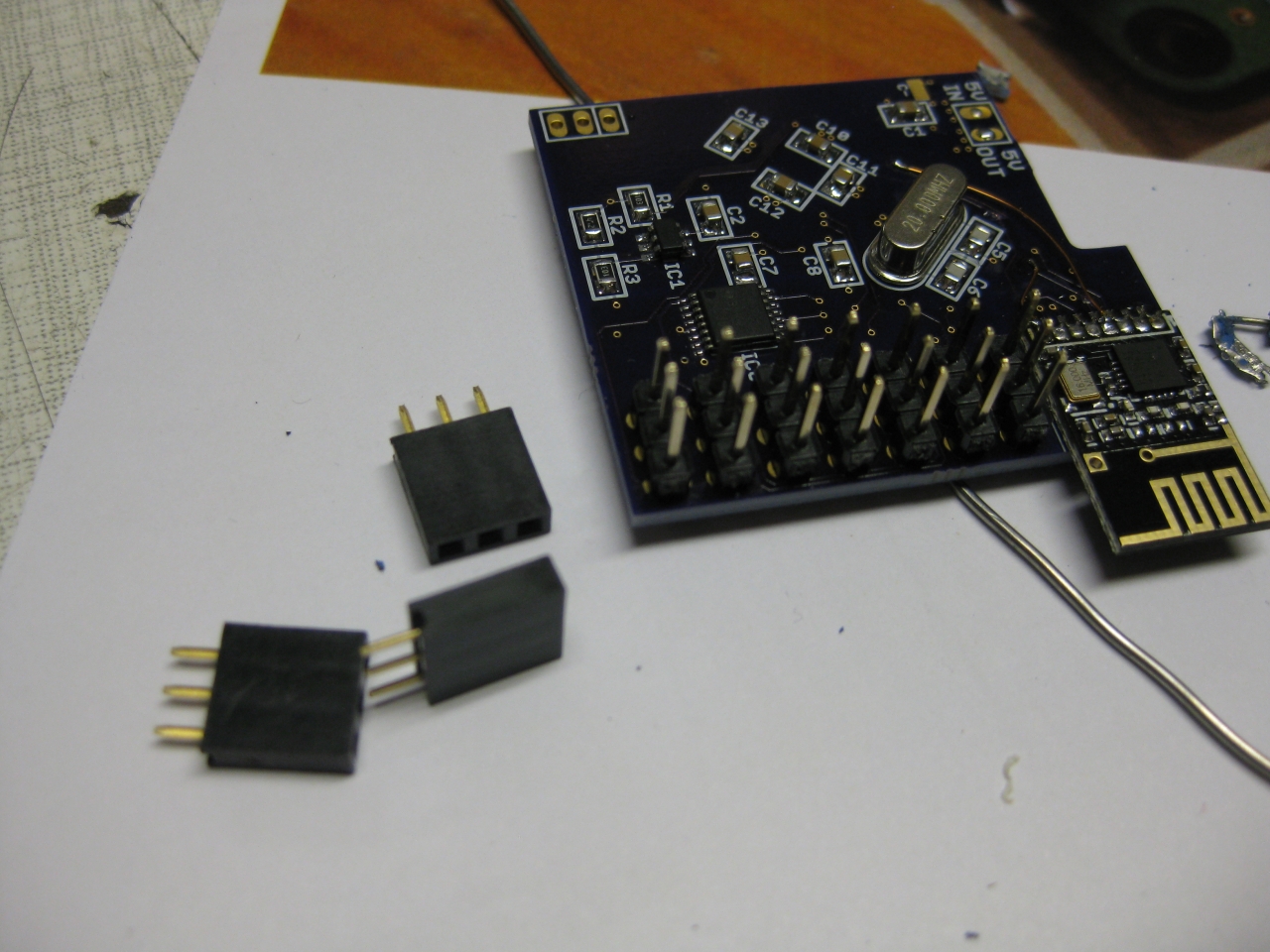
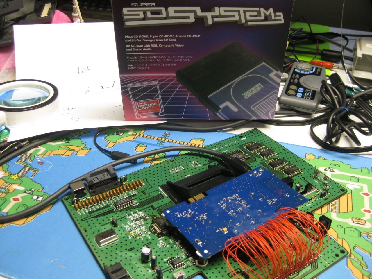
    It holds enough space to put a complete SuperSDSystem3 inside.
    Now its possible to have the complete PC Engine Software Library including all CDs in one unit and it looks like stock level.

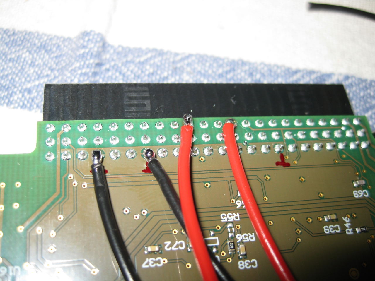
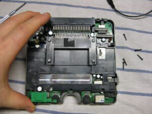
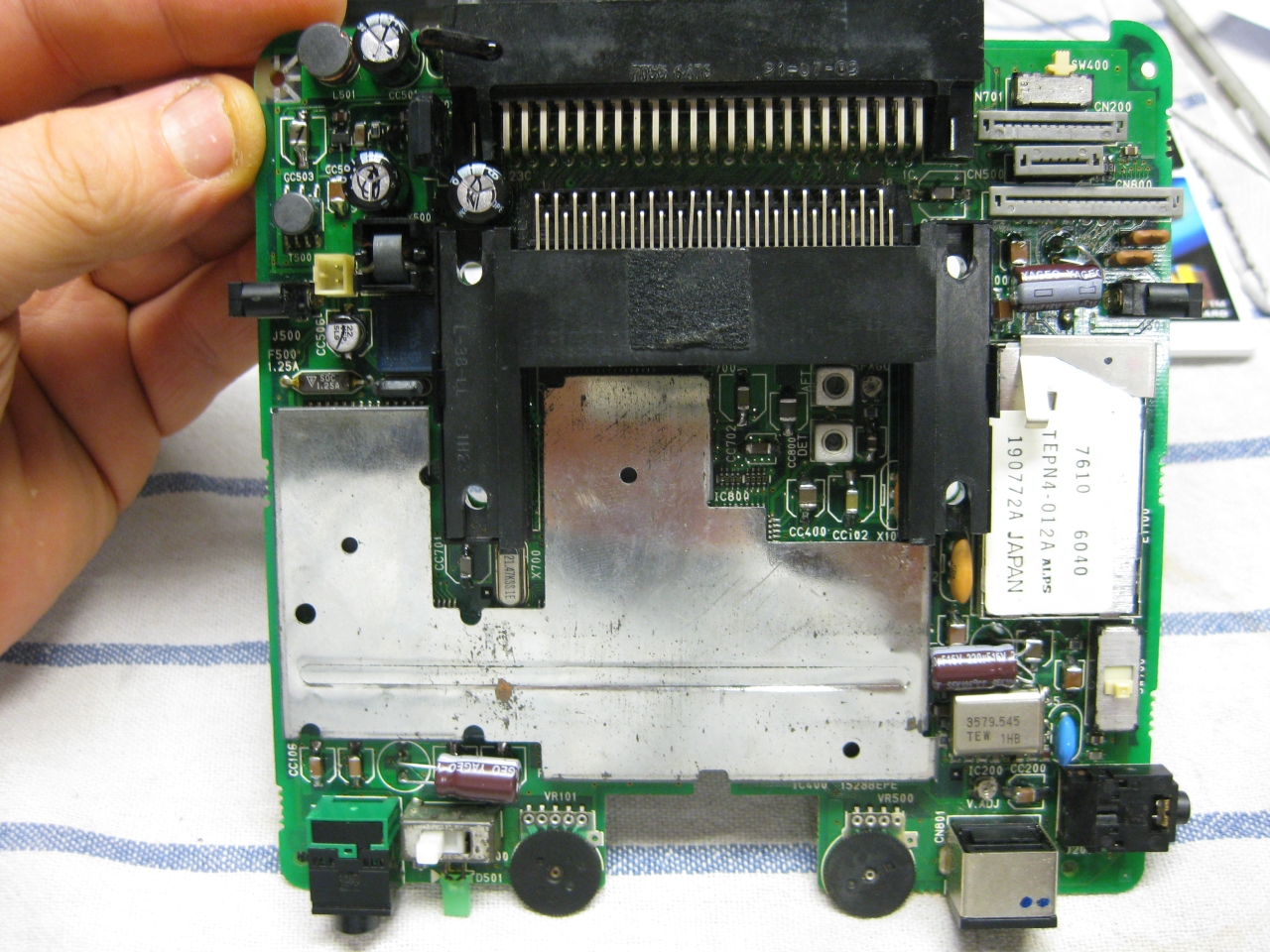
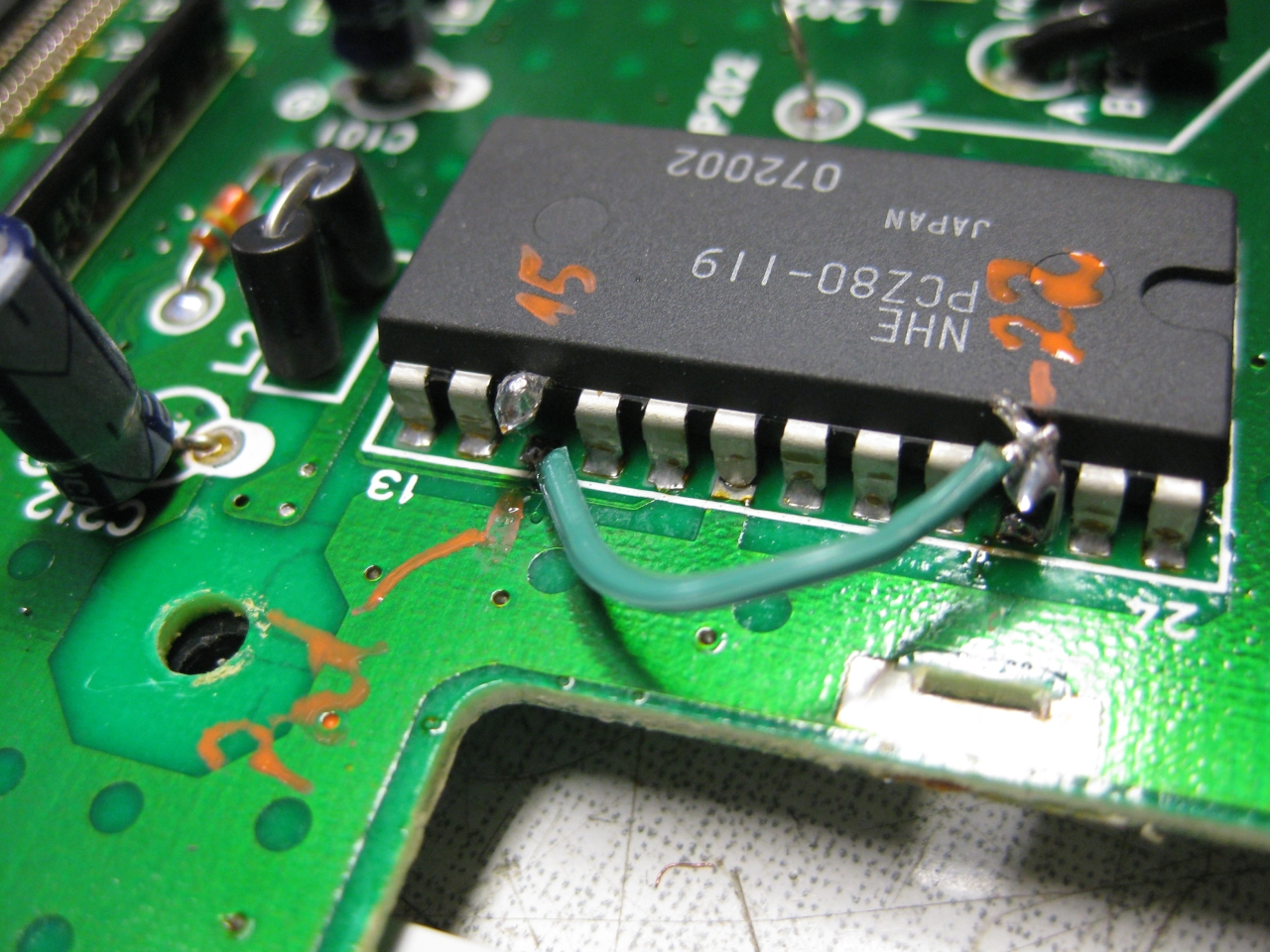
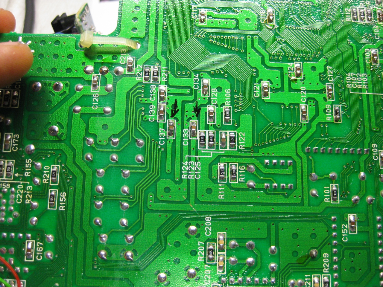
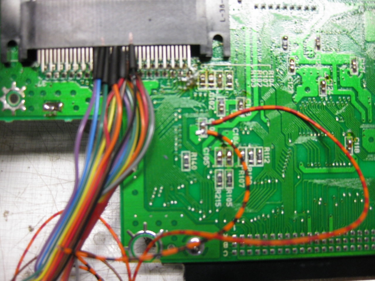
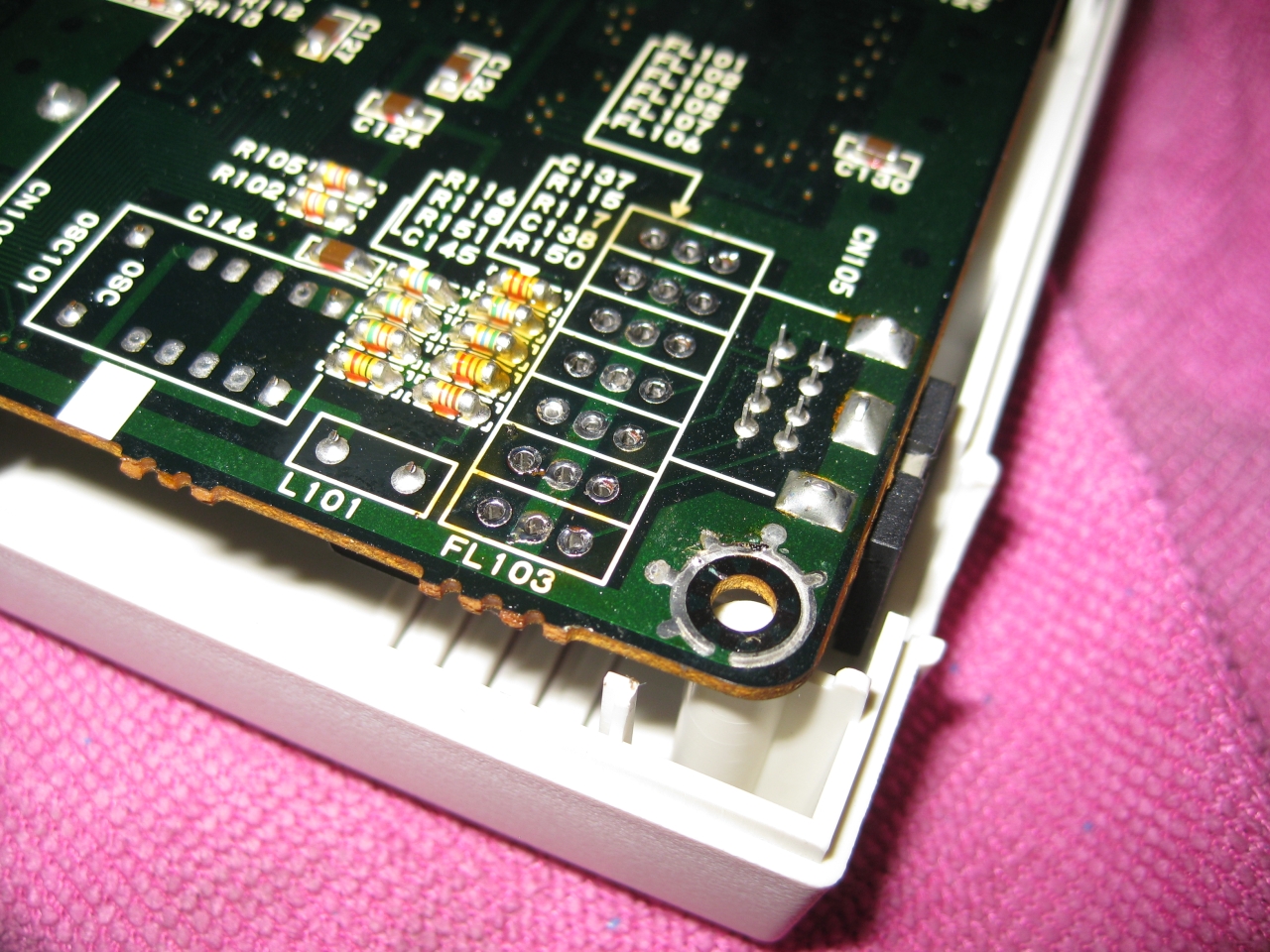
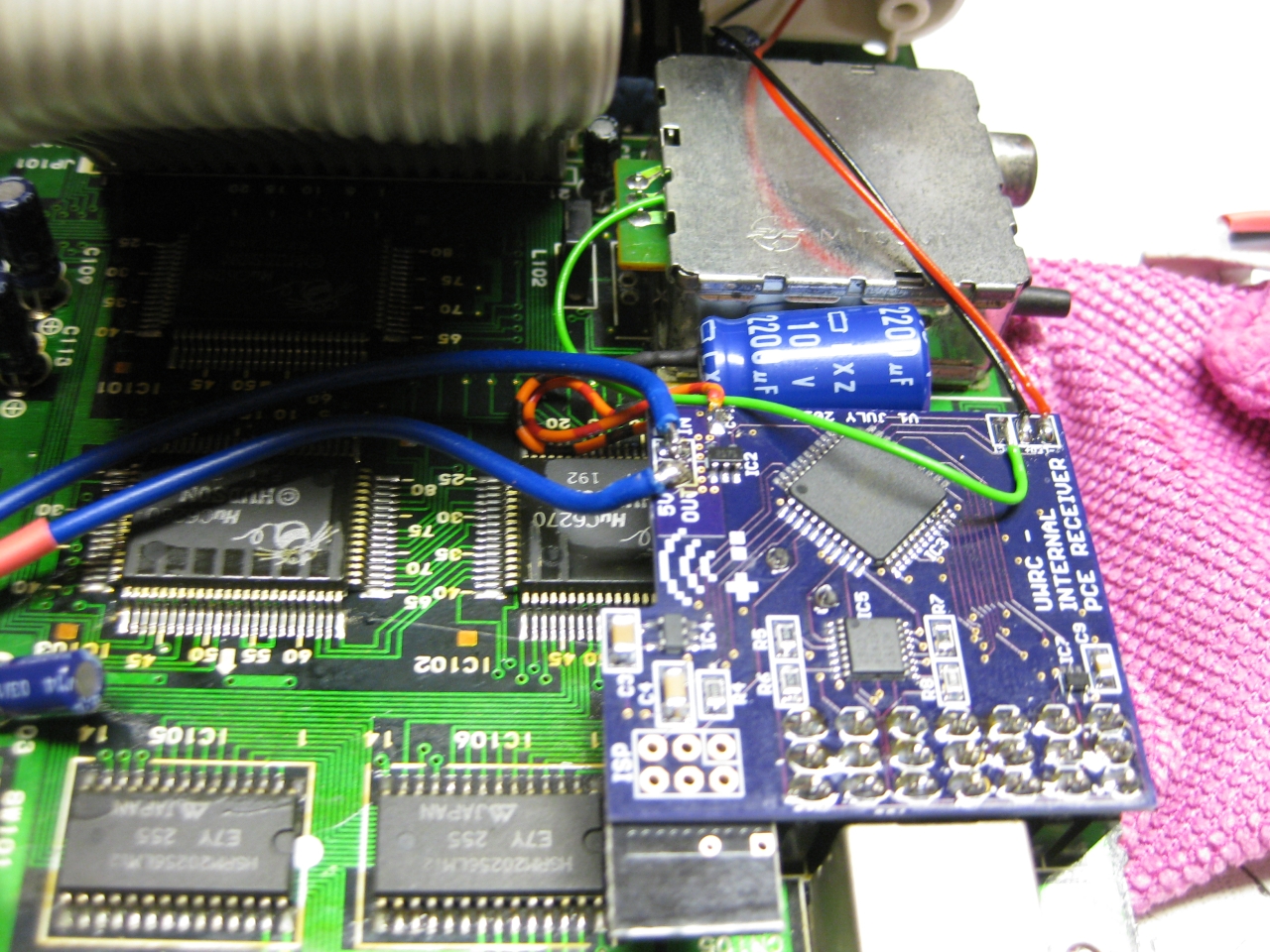
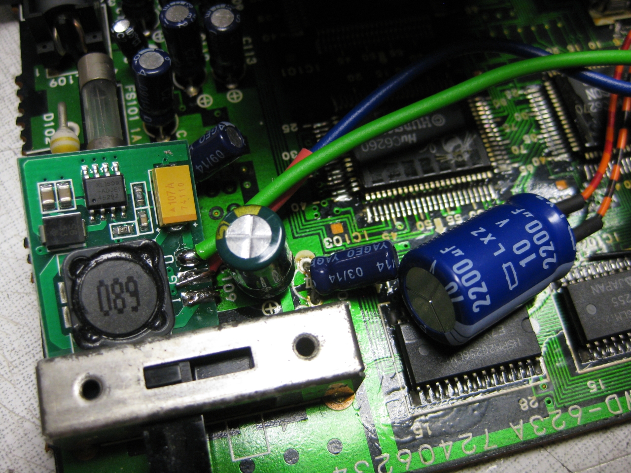
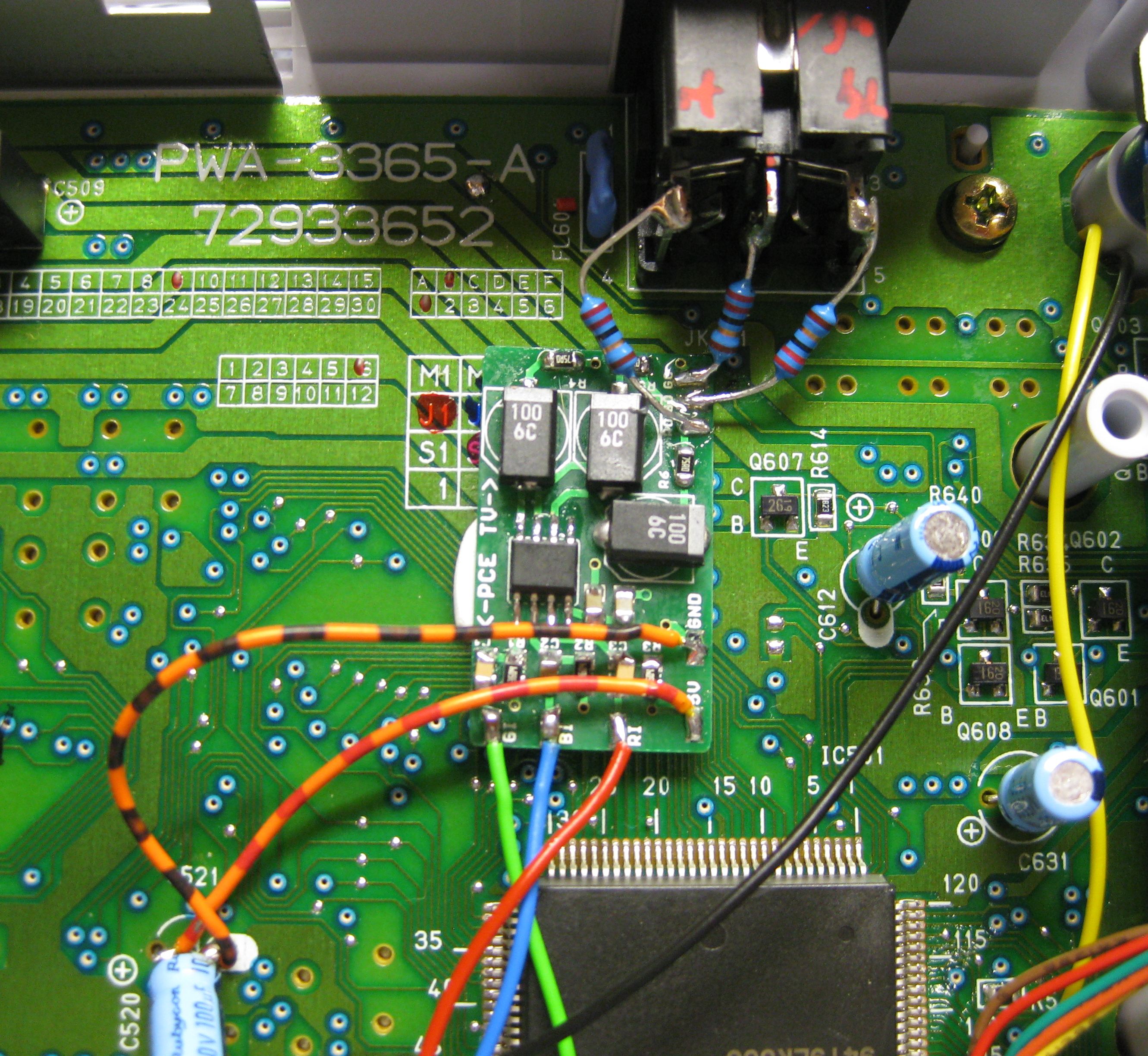
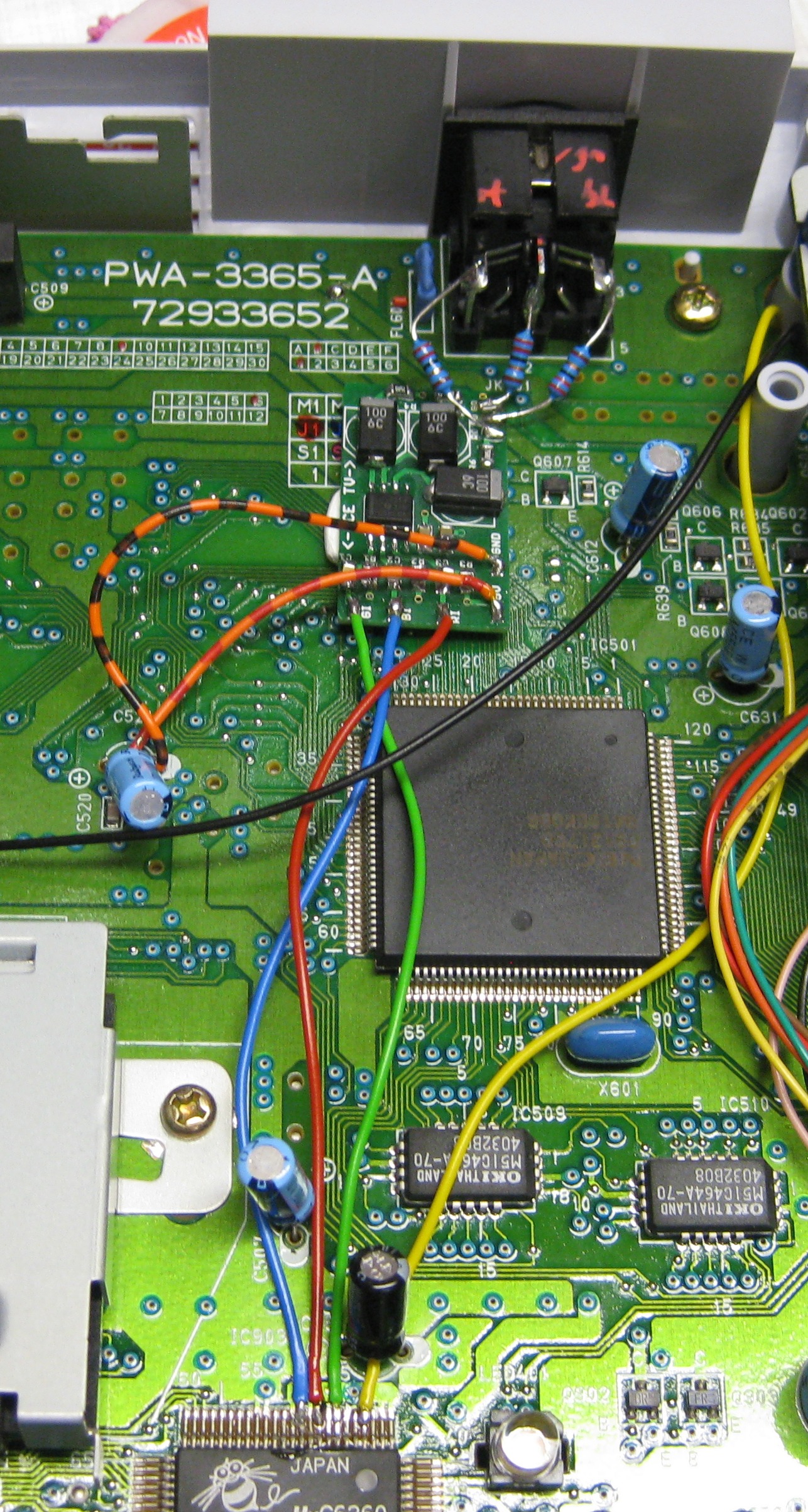
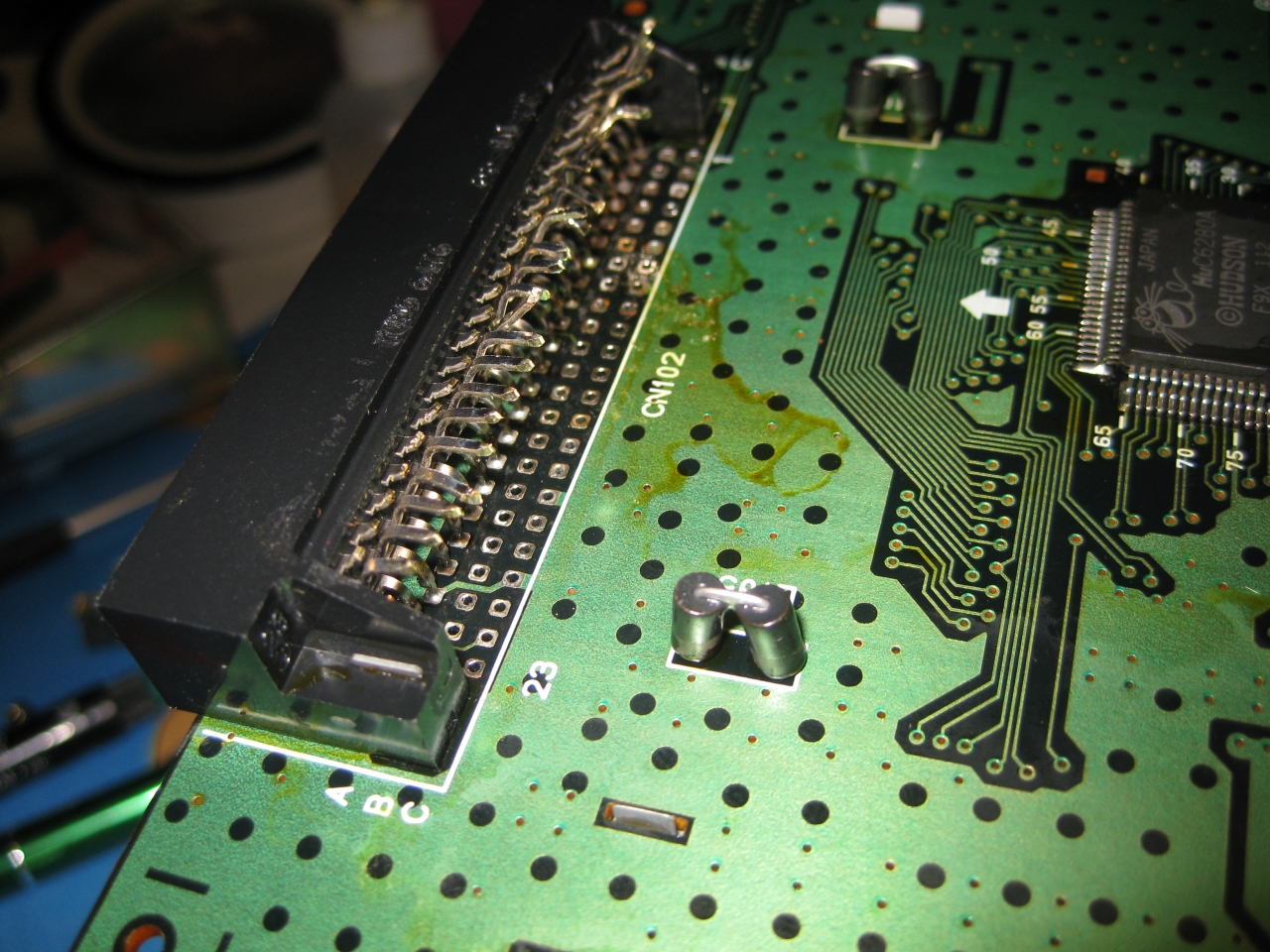
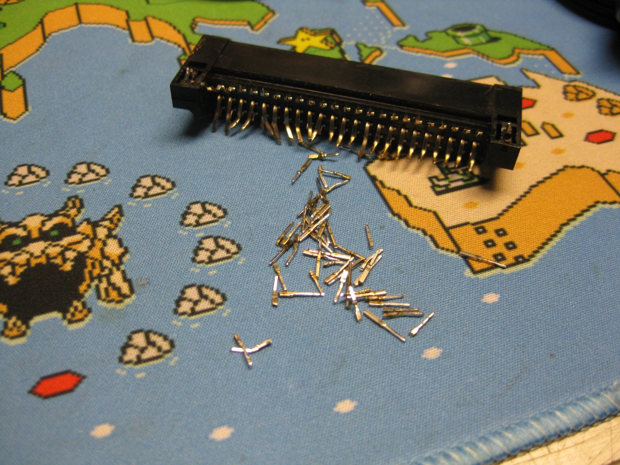
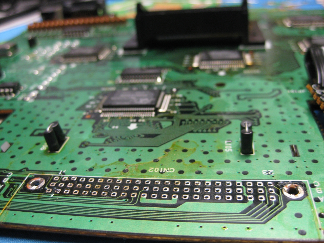
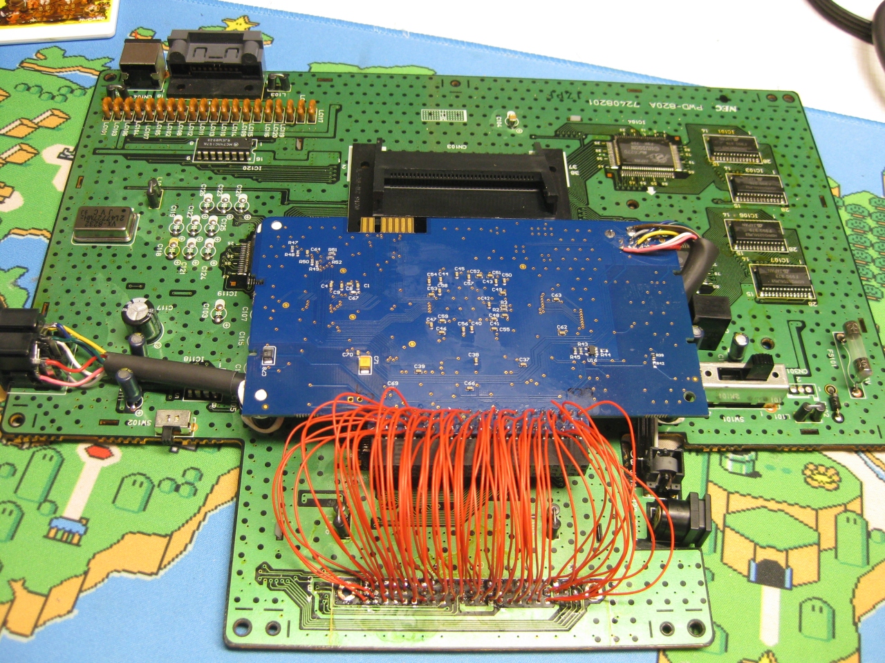
    Removing the original Extension Bus makes it easier to put all the wires to the SuperSDSystem 3.

    SuperGrafx9

    SuperGrafx8

    SuperGrafx7

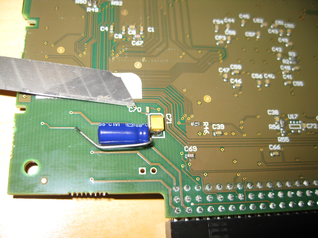
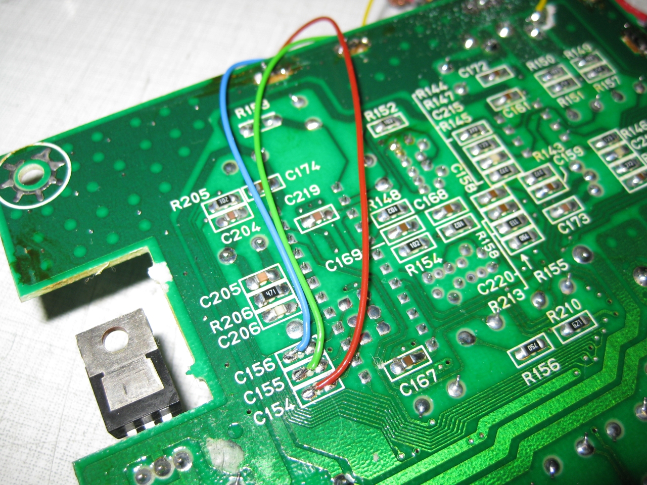
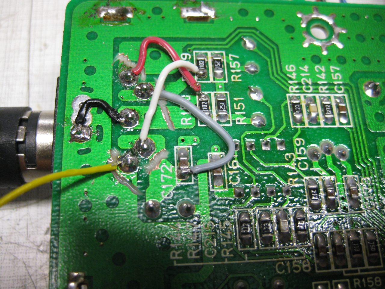
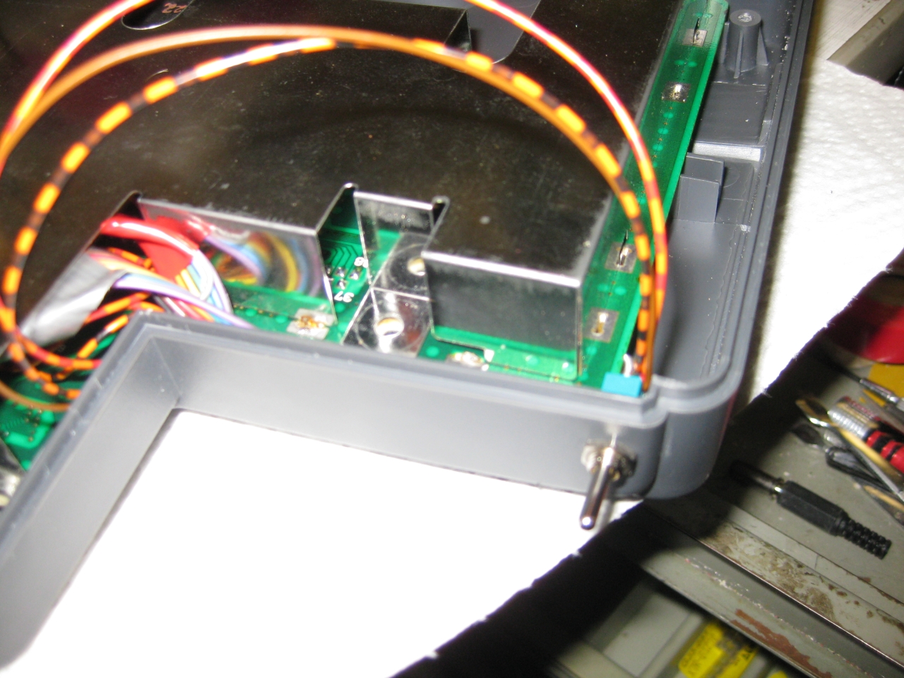
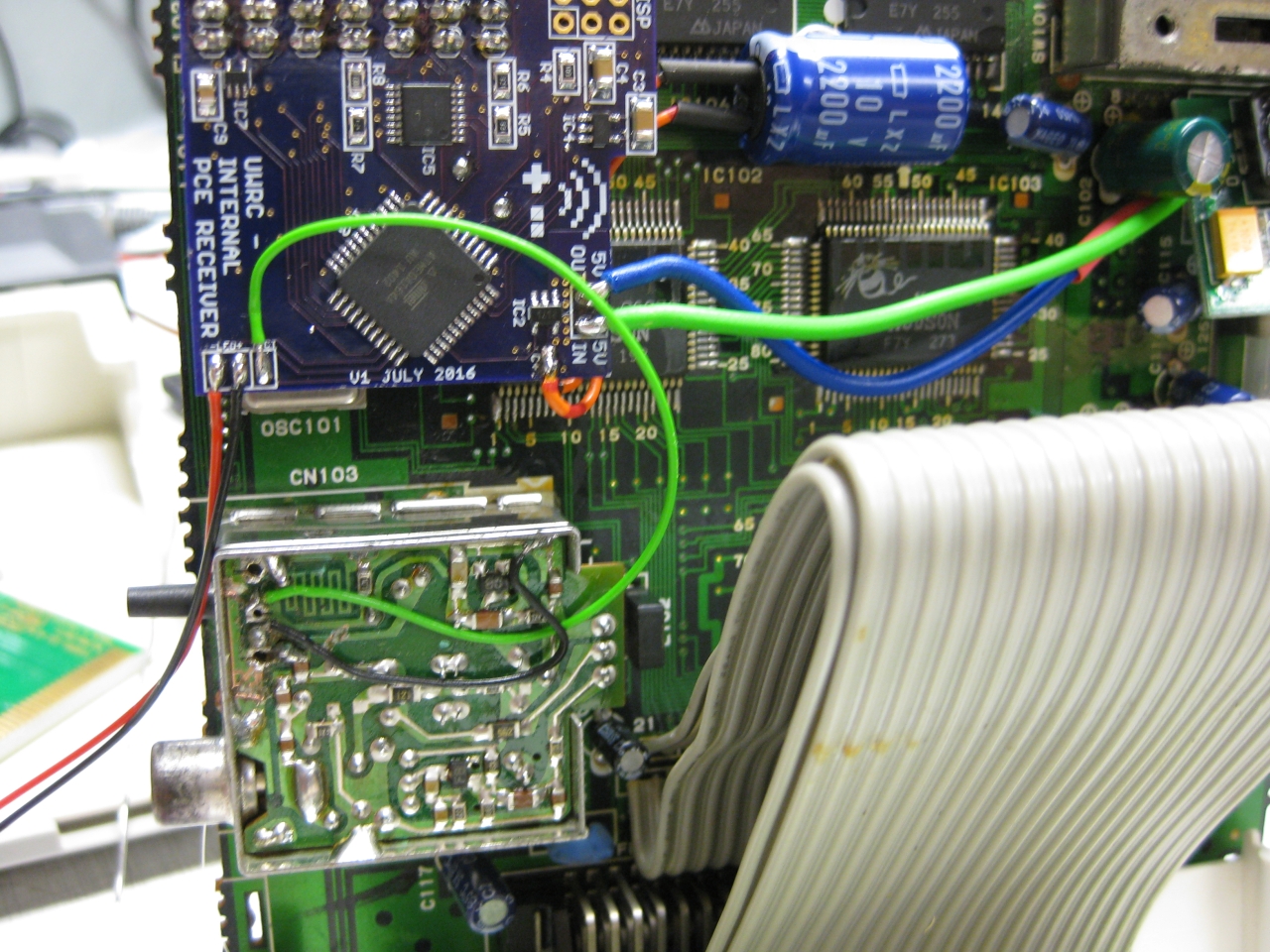
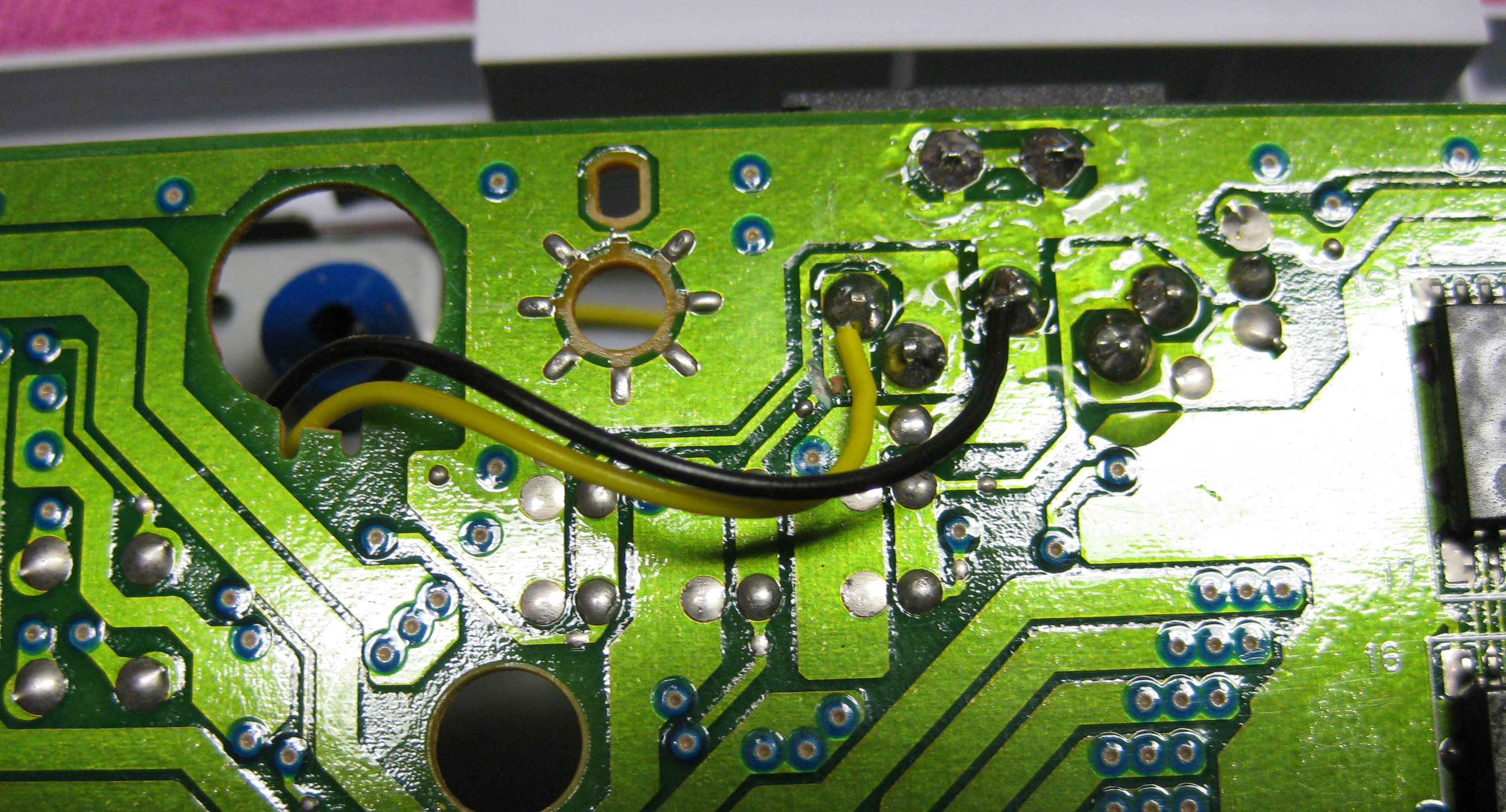
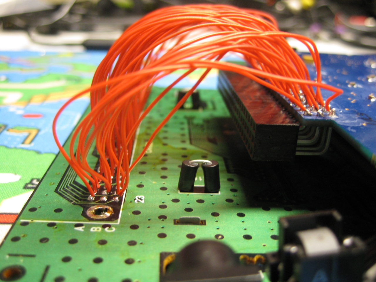
    A lot of wires needed

    SuperGrafx3

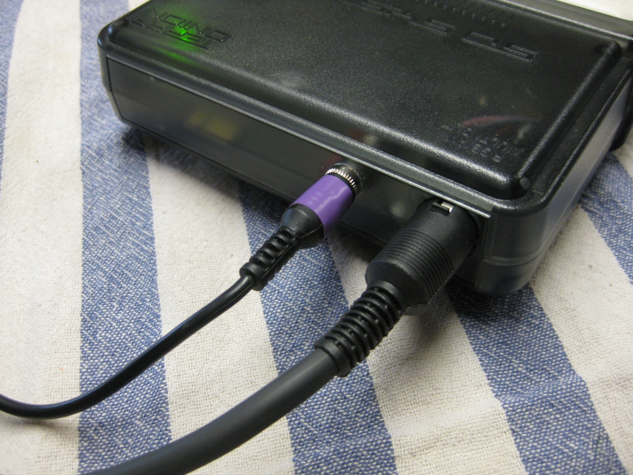
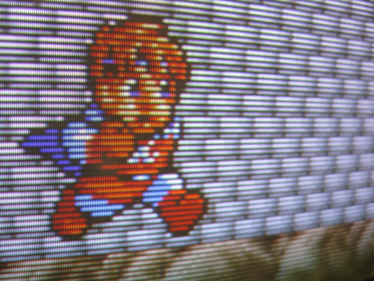
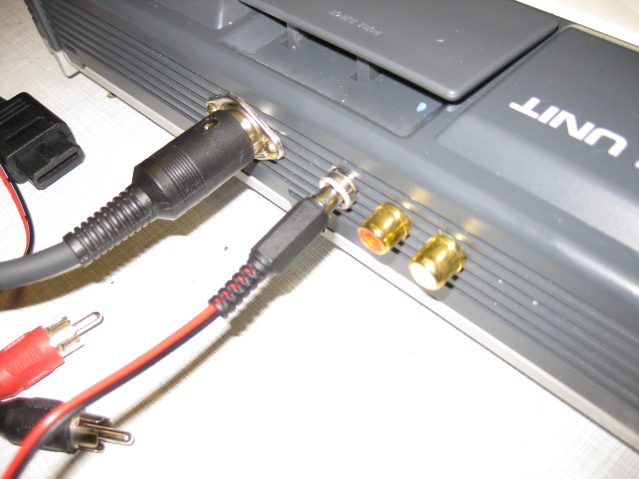
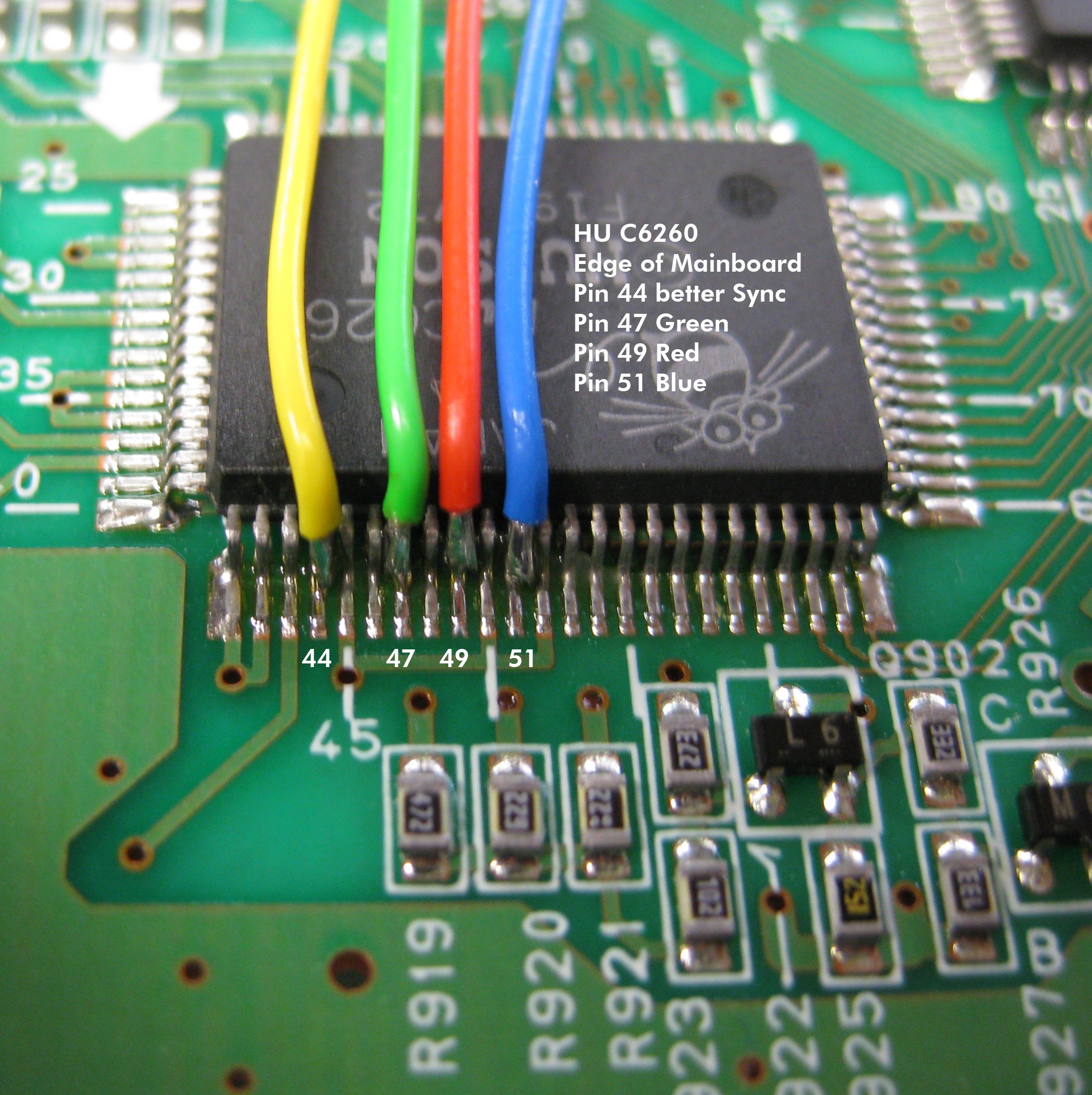
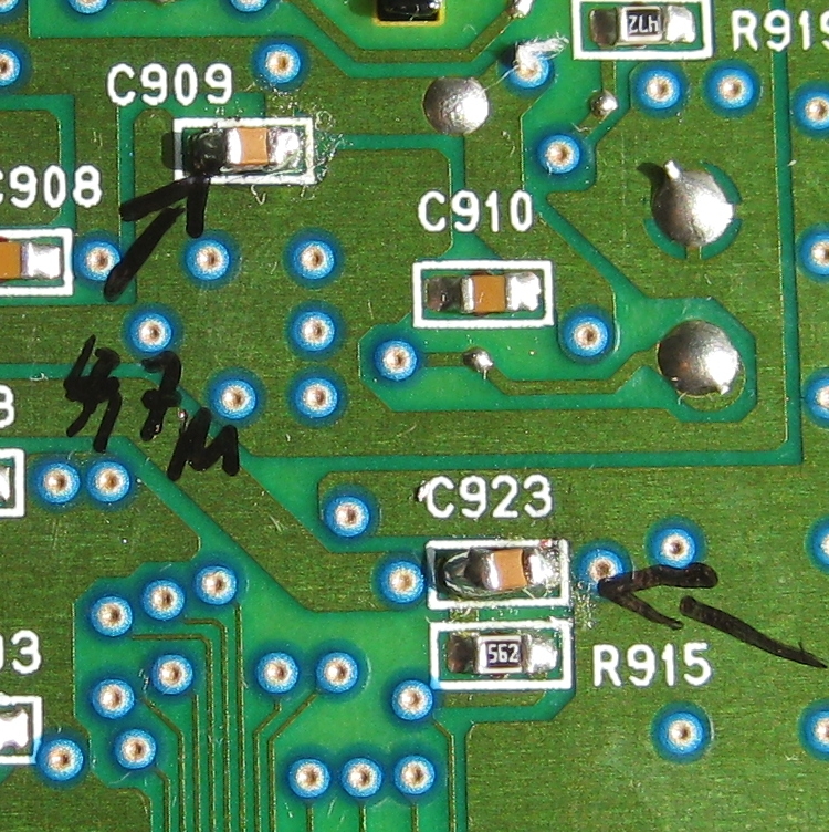
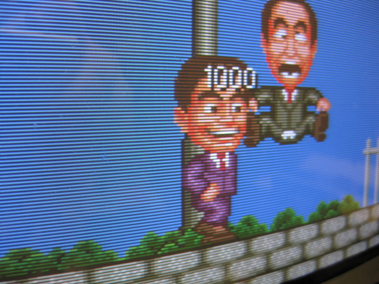
    testing with original RGB Output from the SuperSDSystem3

    SuperGrafx6

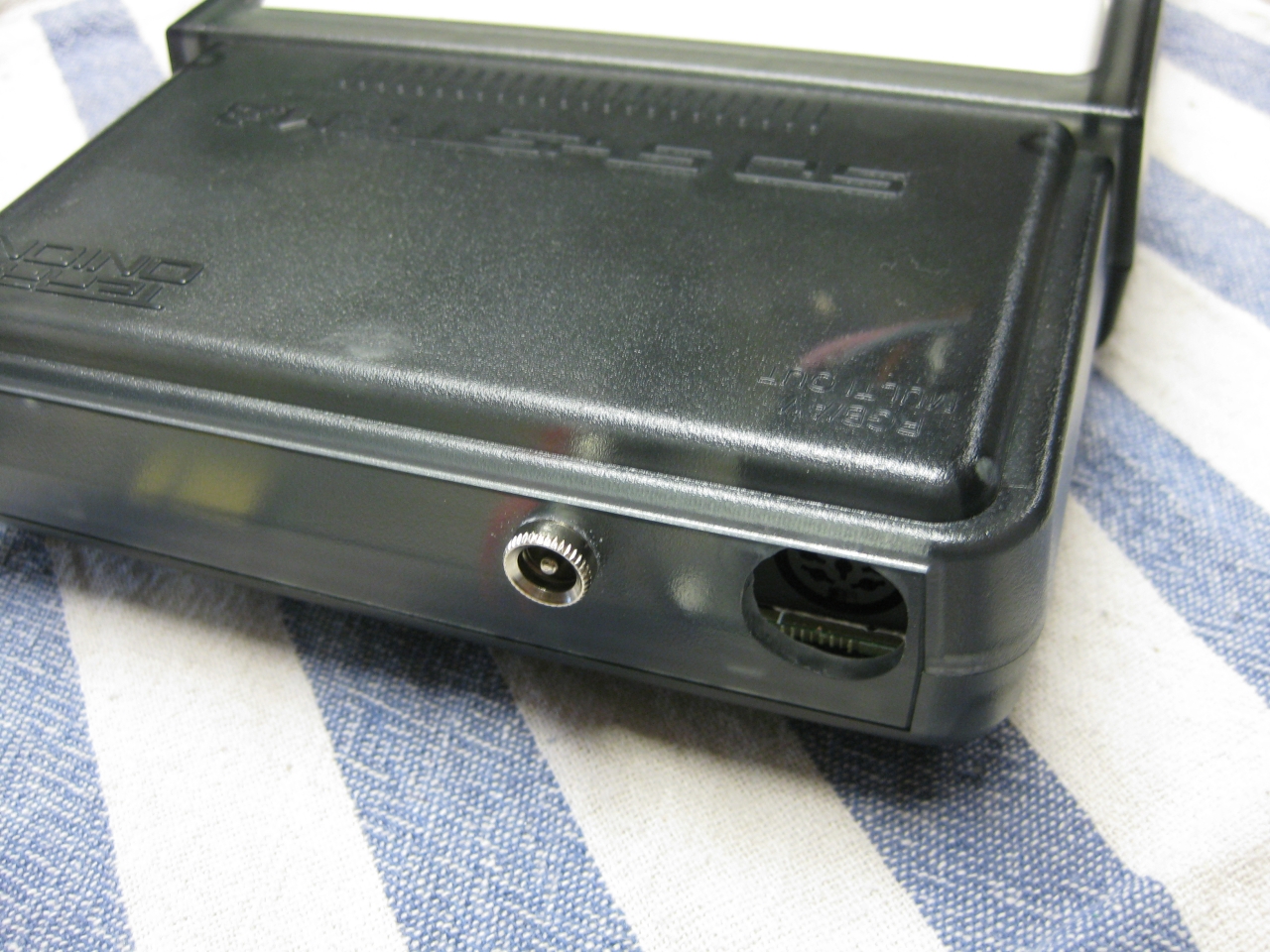
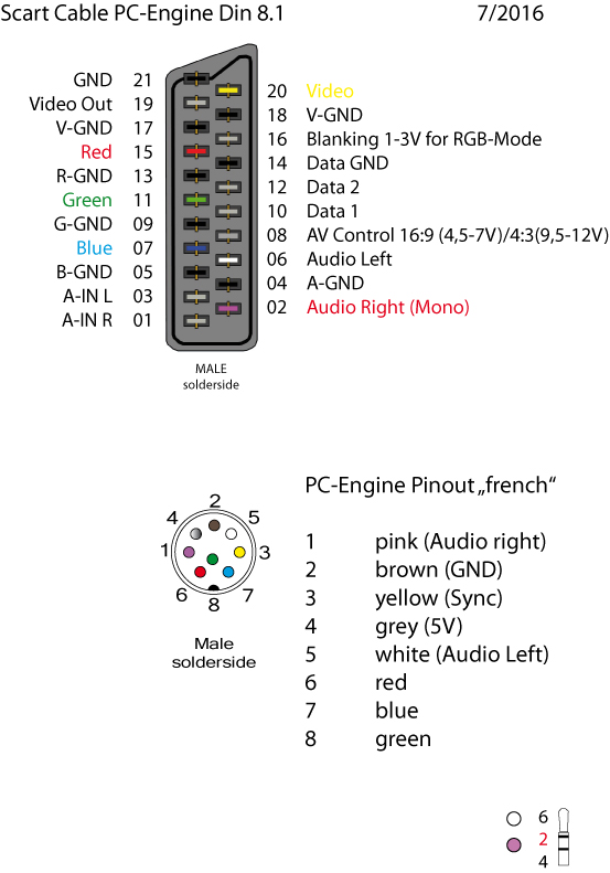
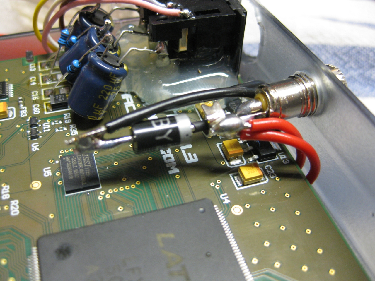
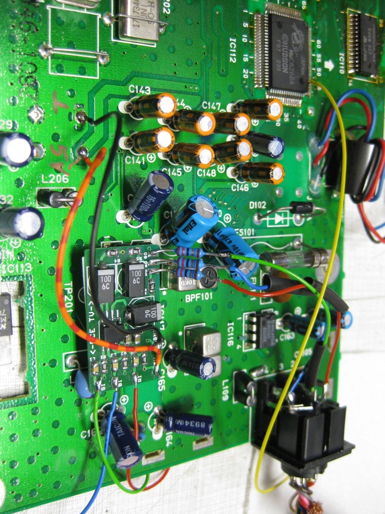
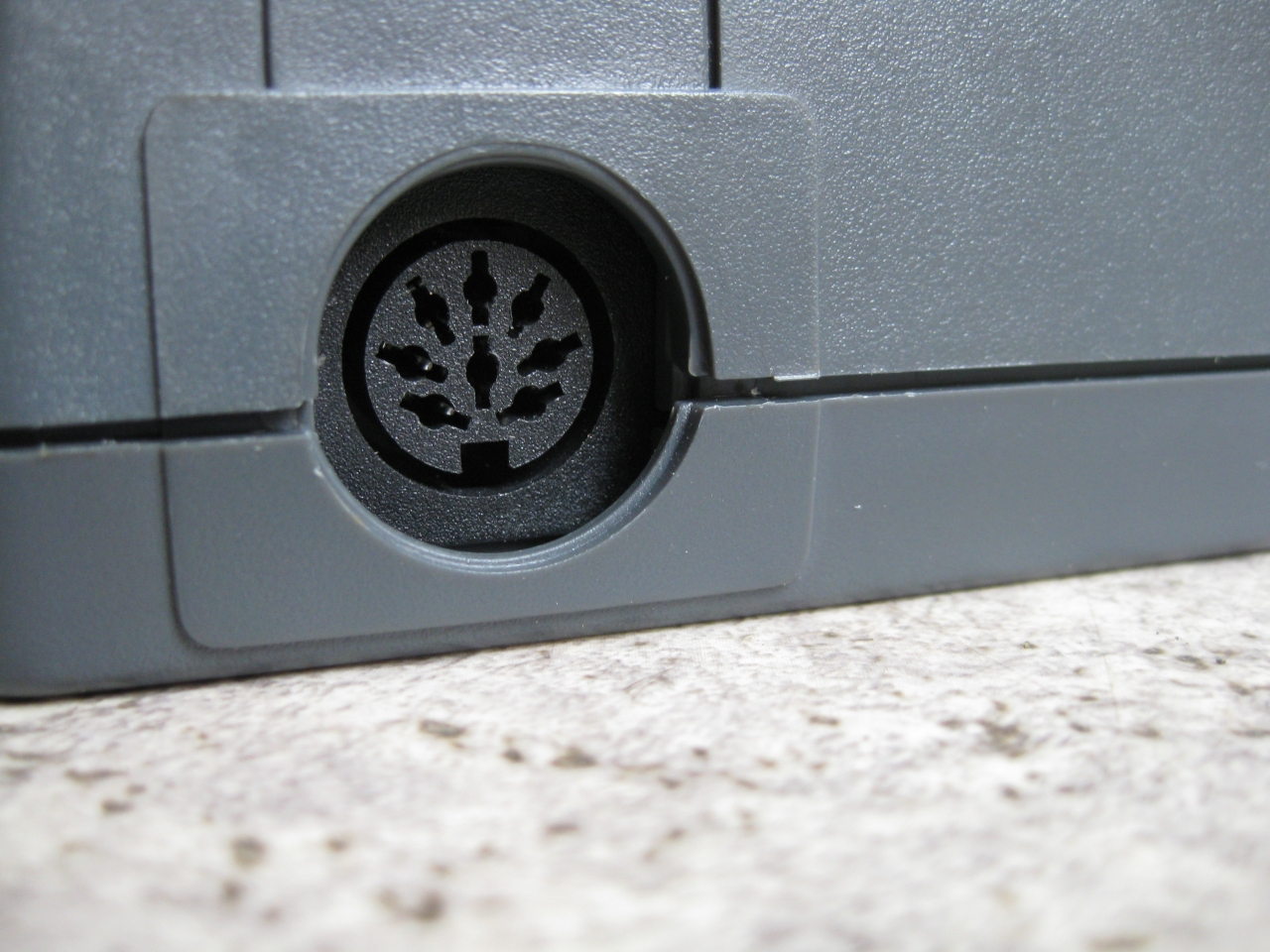
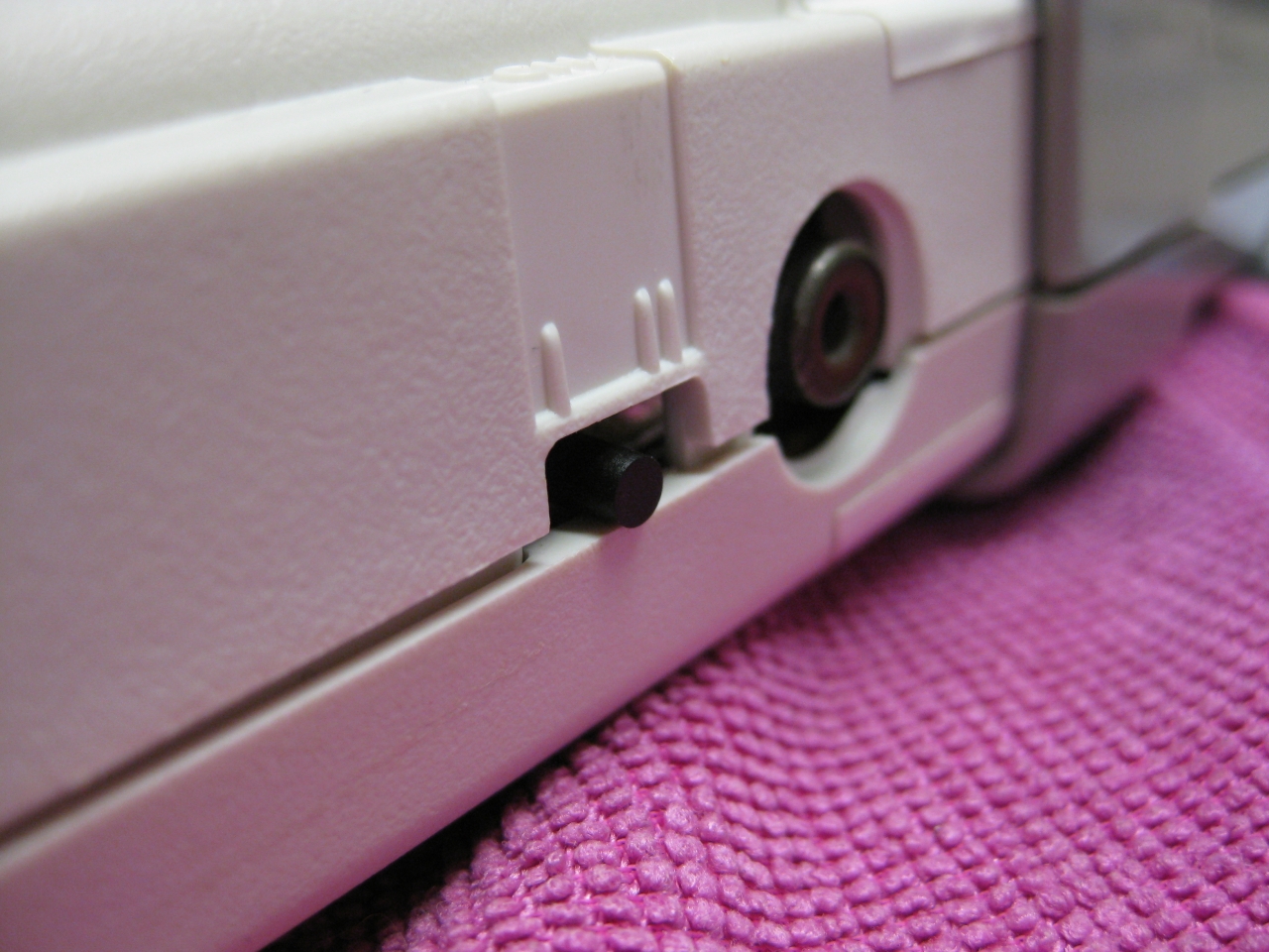
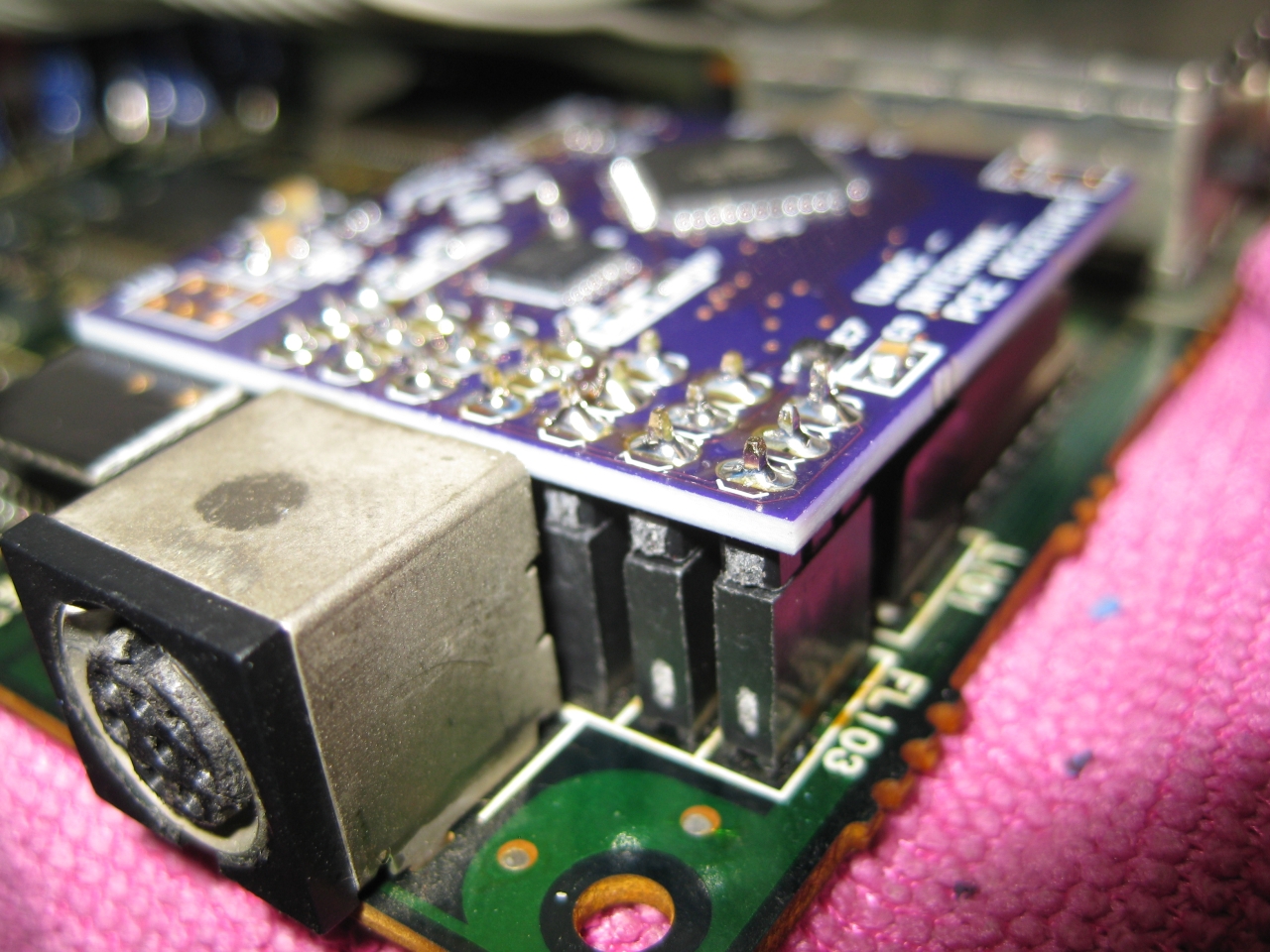
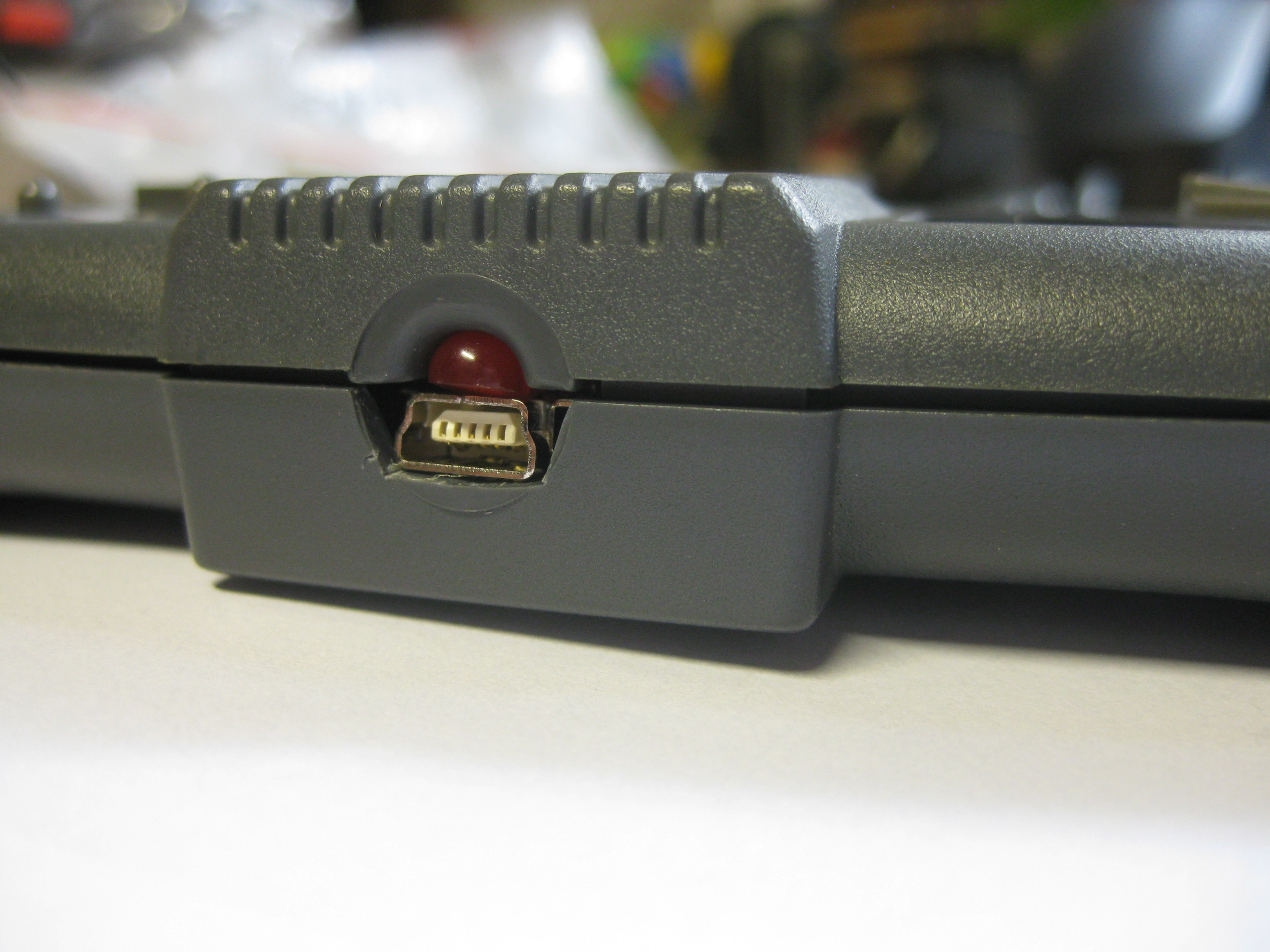
    Removing the original DIN A/V Connetor and replacing with a DIN 8.1 to make RGB
    Output via the original A/V Port

    SuperGrafx5

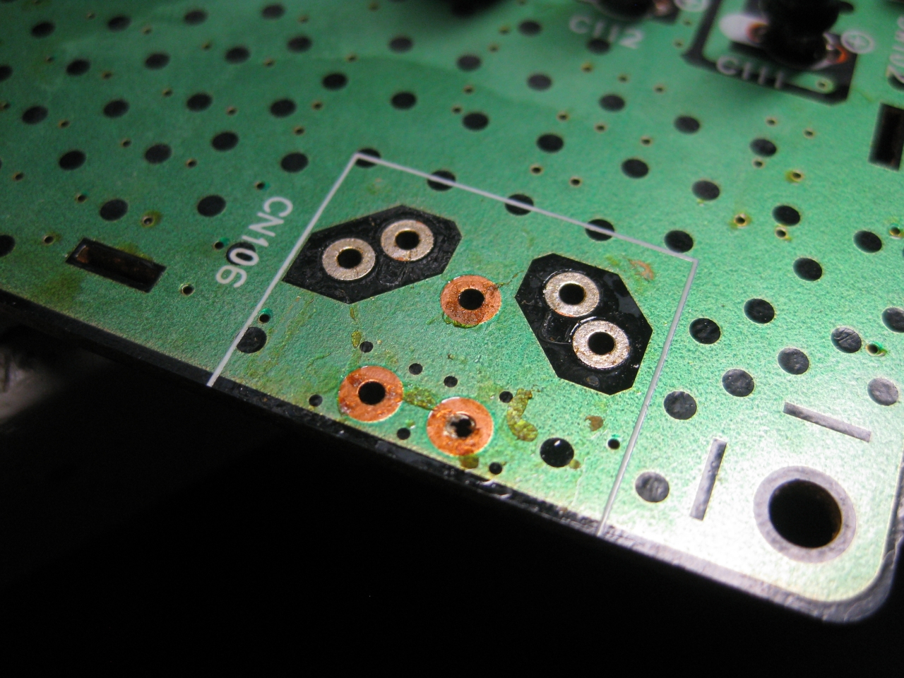
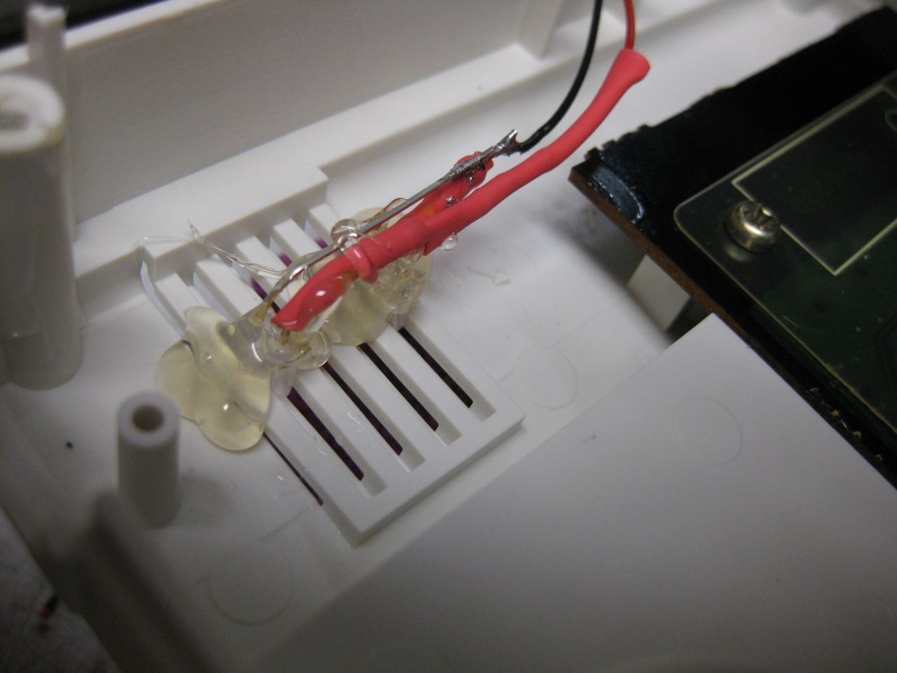
    a shieded cable to the A/V Port

    SuperGrafx4

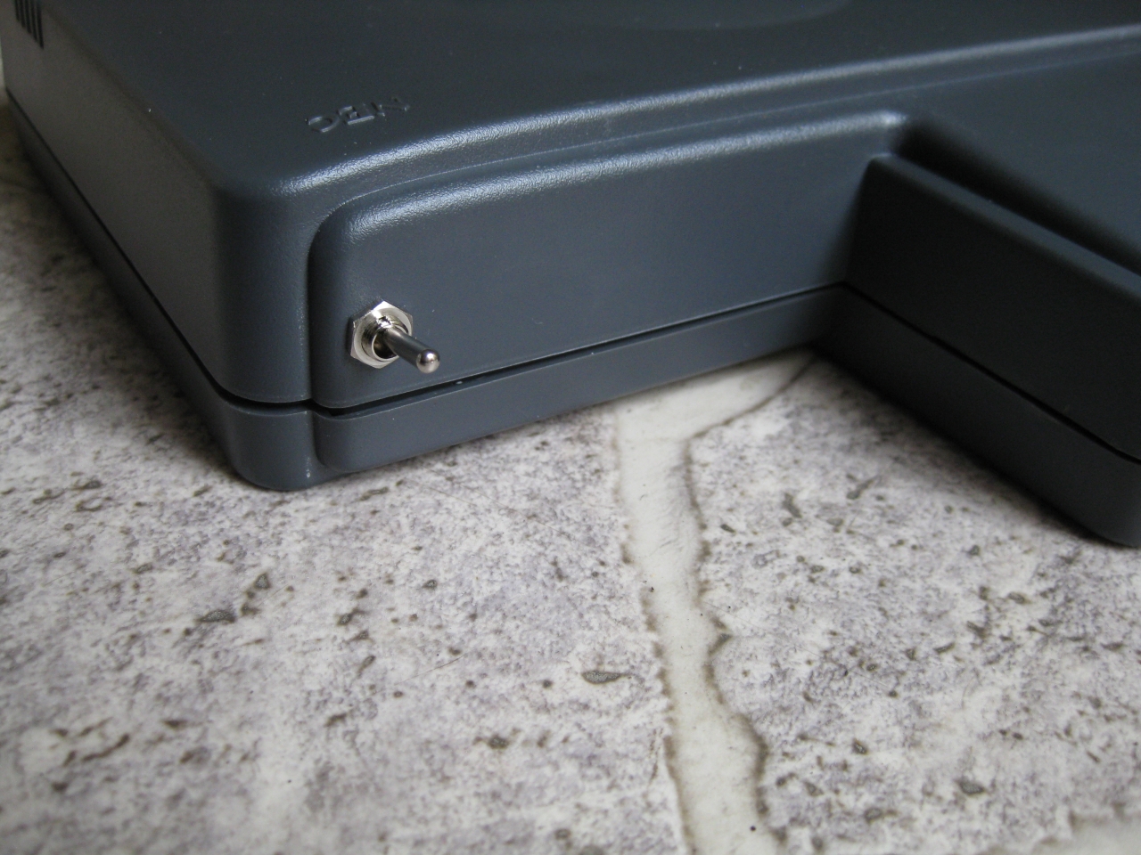
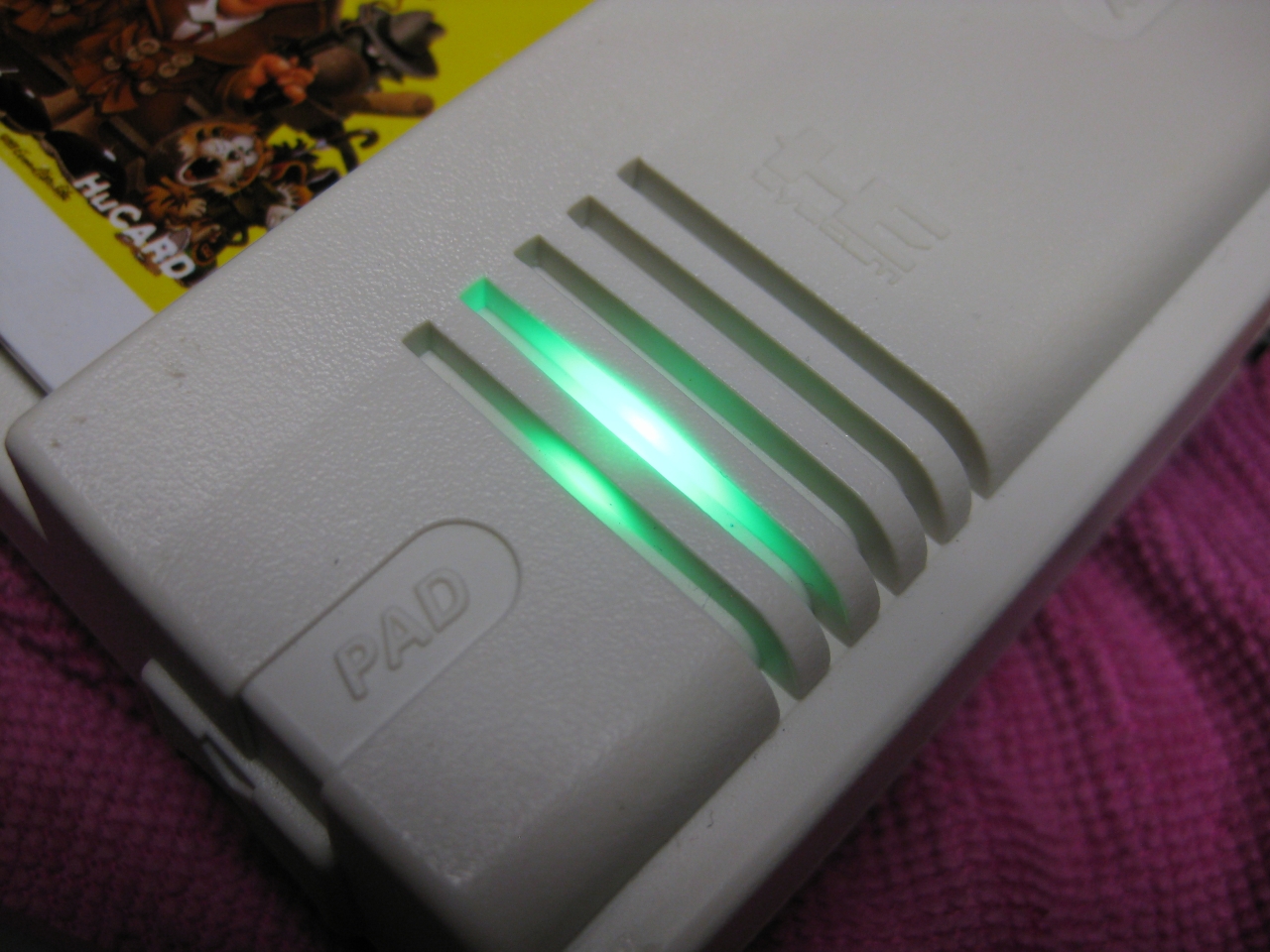
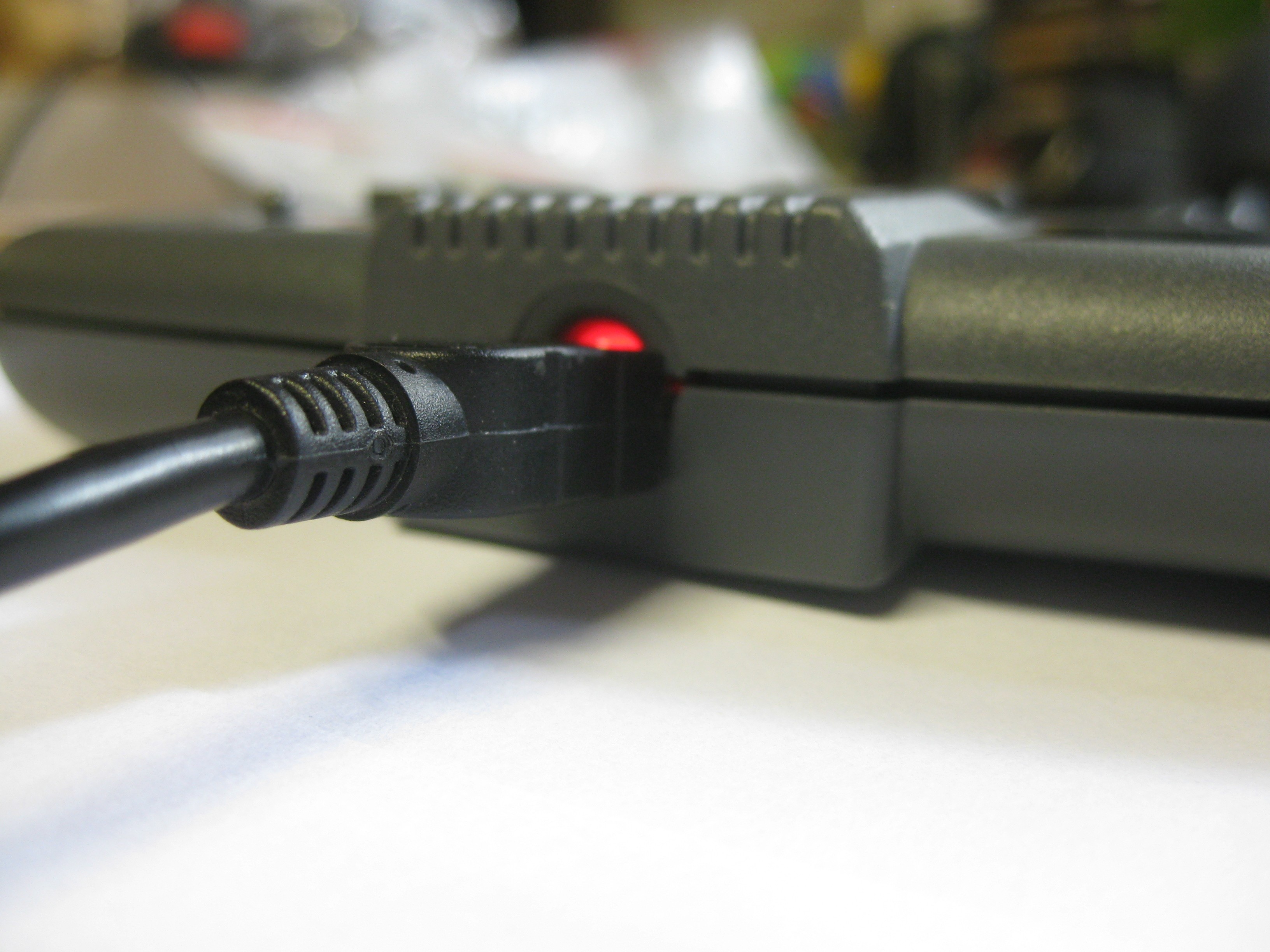
    and with the cover on the backside you see „nothing“.

    SuperGrafx1

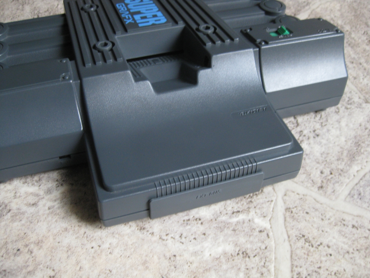
    We call it SuperSDSystem3 inside 😉


  • DIN 8 and Power from Super SD System 3

    As I have open the Super SD System 3 for the Audiofix. I change the Mini Din A/V Connector to my common 8 Pin DIN connector, because I have a lot of consolse fitted with this same connector.

    PCE_PowerInputviaEx_Port4

    I am not a friend of cables from different sides of a console. So i put both RGB and Power supply in the back and have a nice looking PC-Engine Combo

    PCE_PowerInputviaEx_Port3

    Pinout RGB


    scart_PC-Engine_French_Layout_2016

    The Powersupply +9V at the red wires GND at the black wires

    PCE_PowerInputviaEx_Port1

    I used a big diode to avoid wrong input voltage

    PCE_PowerInputviaEx_Port2

    PCE_PowerInputviaEx_Port5

  • Super SD System 3 Audio Fix

    you can hear a lot of digital noise, when accession SD Card. This fix solve it and we have silence 🙂
    With the help of a single 10uF 10V Elko its done. Minus at the yellow Cap, Plus to the via

    SSDS3Audio_Fix10u10V

  • Today I revived a the holy grail of PC Engine Hardware a PC Engine LT.

    PCE_LT_ (3)

    Only 5 screws and remove 3 ribbons you will get the main PC Engine Board

    PCE_LT_ (11)

    Because of its age the Caps are brocken and need a replacement.

    After some exchange in the power area it works again 🙂


    PCE_LT_ (10)


    look how bad it looks because of leaking caps


    PCE_LT_ (8)


    how ugly it looks. Some alkohol for cleaning


    PCE_LT_ (6)


    PCE_LT_ (5)


    exchanging of most caps to kerkos


    PCE_LT_ (4)


    after recap

    LT jailbarfix


    jailbarfix too with replacement of 2 kerkos into: 4,7uF 16V or 25V


  • Jailbarfix Super Grafx

    not a big thing replace these 2 caps with 4,7uf/16V in SMD eg. G0805 and the jailbars are gone.

    you will find them on solderside from the PC Engine Super Grafx.

    jailbarfix_supergrafx

  • Modding PAL TurboGrafx

    I got some rare NOS TurboGrafx in 50Hz PAL Version.

    img_0476
    What can we do with this kind of PC-Engine

    a) Speedup and change it to 60Hz

    -Exchange Osscilator X201 to 21.47727Mhz
    -cut Pcz80 Pin 15
    -Solder wire from Pad pin 15 to Pin 22

    img_0442

    b) RGB bypass for best picture

    I took the RGB Signal from C154 to C156 after removing the Kerkos. The wires leads directly to the Hu6260 RGB-Out

    img_0435

    using the rgbbypass PCB

    img_0443

    yellow wire to desoldered PIN 44 from HU6260 (C-SYNC)

    I am using an old „french“ pinput from the 90’th. So I have to reroute some cirquits

    scart_PC-Engine_French_Layout_2016
    Desolder Din and cut GND on Partsside for make standard french Version of Din8 Cable working.

    img_0455

    Cut 5 Din Via circuits and wire as shown here
    red audio 2 (right), white Audio 6 left, grey 5V
    yellow desoldered Pin 44 from Hudson 6260 CSYNC

     img_0475

    c) Jailbarfix

    exchange C137 and C133 to 4,7uf/16V

    jailbarfixpalturbografx


    img_0469


    d) jap/eng switch

    you need to switch 8 wires (15,16,17,19,20,21,22,23). I done it with two  analog switches  MC14551BCP

    img_0458

    img_0462


    img_0473


  • internal PC Engine UWRC Receiver


    I used my IFU-30 Unit, so there was no need to remove the RF Unit. As I didn’t wanted some wires to the left or right side.

    I put all needed connections to the rear side. Power, RGB-Out, Audio Out.


    IMG_0073


    I opened the RF-box removed the orignal switch and replaced it with UWRC switch.

    ground to one side and the other side of the switch to the uwrc board

    IMG_0028

    IMG_0032

    IMG_0034

    IMG_0033

    IMG_0067

    thanks again to micro, for his great Idea how to make the UWRC plugable, by removing the filters.

    IMG_0021

    IMG_0020

    IMG_0022

    IMG_0051

    green wire uwrc controll switch, red and black to the signal led combo I created at the upper side

    blue „bigger“ wires to the 7805 replacement for swiching the pce off/on

    IMG_0041

    a red 5mm led and a green 5mm led dremel work and to the ventilation grid

    IMG_0044

    IMG_0061

    IMG_0058

    IMG_0062

    no more heat -> replacement of the 7805

    IMG_0038

    Great feature, you can power off and on the PC-Engine via holding select and Run for around 1sec. Ideal for users of everdrives. Hope this feature will find his place in all new internal receivers from micro 😉

    Final Pic

    IMG_0072

  • UWRC PC Engine Shuttle Controller

    A futuristic styled Controller for the PC-Engine Shuttle. Now its time to make it wireless.

    thanks to the PCB of micro and some reposition of the led usb powersupply it works great.

    I put it at the hole of the original wire and with some hotglue it works

    shuttle_1

    shuttle3

    shuttle_2

    shuttle4

    shuttle6

    shuttle5


  • PC Engine Duo R/RX RGB Mod with bypass PCE-TV

    Nothing really new, only to see how to add THS Amplifier working in a Duo R / RX.

    I used Pin 44 of HU C6260 C-Sync for Sync. So you have to cut the Video Signal to the Din Connector (yellow wire).

    Black wire is optional, for „more“ GND


    duo_rx_1

    For the Din Pinout I used the old French Layout born in the 90ths. With RGB added to the 3 new Pins of the Din 8.1. The rest of Pins are untouched (exeption C-Sync)

    3 resistors 22 Ohm are used for make PCE-TV work to output around 0,7V. The PCB is the 1st Revision of micro. Power is taken from a Elko nearby. (orange/black=GND, orange/red=5V)

    duo_rx_4


    duo_rx_2

    duo_rx_3

    Scart Pinout

    scart_PC-Engine_French_Layout_2016

    Jailbars removement

    After checking the picture there are jailbars 🙁

    After replacement of two  capacitor the picture is great.

    replace C909 and C923 with 4,7uf down under Hu C6260

    jailbarfix_Duo_R


    IMG_8818

    You final reward will be 1000 Points 🙂

    Wireless Rules

    thanks micro

    wireless-pce-rules

  • UWRC PC-Engine Cordless Controller

    I done some ironical way of UWRC 😉
    Here i am using 3 of the 4 Batteries for powersupply of the UWRC, because of the max. voltage of 5,5V of the UWRC Board.

    IMG_8597 IMG_8599 IMG_8602 IMG_8604 IMG_8610 IMG_8609 IMG_8608 IMG_8607