Today I have to make a switchless mod for the good old Mastersystem in its original form.
No problem for me, after changing sebs code for Mastersystems few months ago.
After opening you have to go under the mainboard and cut 3 wires of the mainboard
The parts site is holding the pic as usual
I am using the same code I done for the mastersytem2
You have to remove the original 5mm LED and replace it with a RGB-Led with common plus like this one.
The resistors of the LED: 220Ohm. You can use higher ones, if the light is to bright.
Usage:
You can change the Modes via pressing the reset Button of the Mastersystem
If you press the reset button very short -> The Sega Console will do a reset
If you press the reset button longer the Led toggles between red and green.
If you let the button go at red the Mastersystem is set to 60Hz
If you let the button go at green the Mastersystem is set to 50Hz
After removing the shielding you can find the jumper for 50/60Hz and the Country Settings
The default for a europe unit JP3 is set and JP2. You will have to remove any jumper you will find
at JP1, JP2, JP3, JP4.
Some more Info about the Jumper Area:
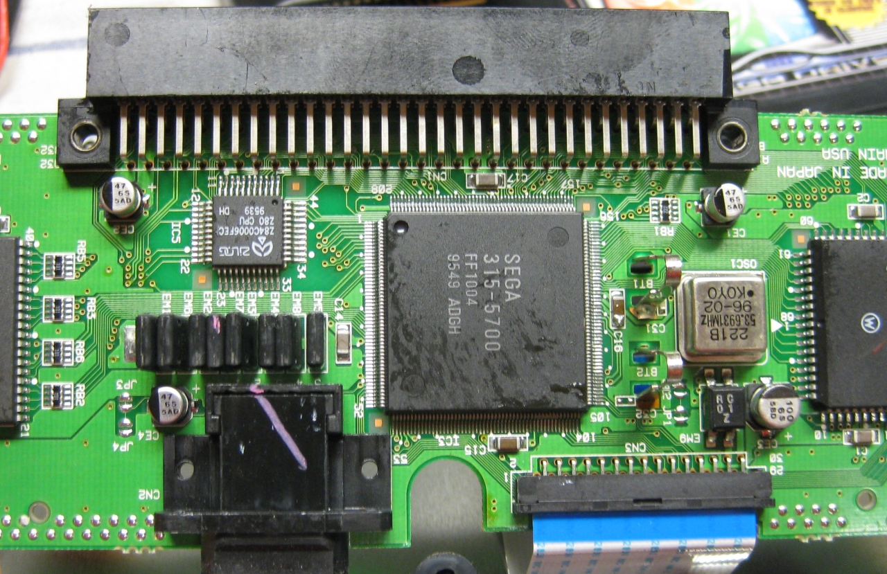
The circuits are going straight to the big SEGA 315-5660 IC
Pin 46 at Sega 315-5560 -> 50/60Hz switching. GND= 50Hz and 5V = 60Hz (JP3, JP4)
Pin 107 at Sega 315-5560 -> Country settings. GND= jap. and 5V = engl. (JP1, JP2)
Now its time to make use of a PIC 16F630 with sebs Code.
red wire 5V, black wire GND, pink wire 50/60Hz, purple wire country setting
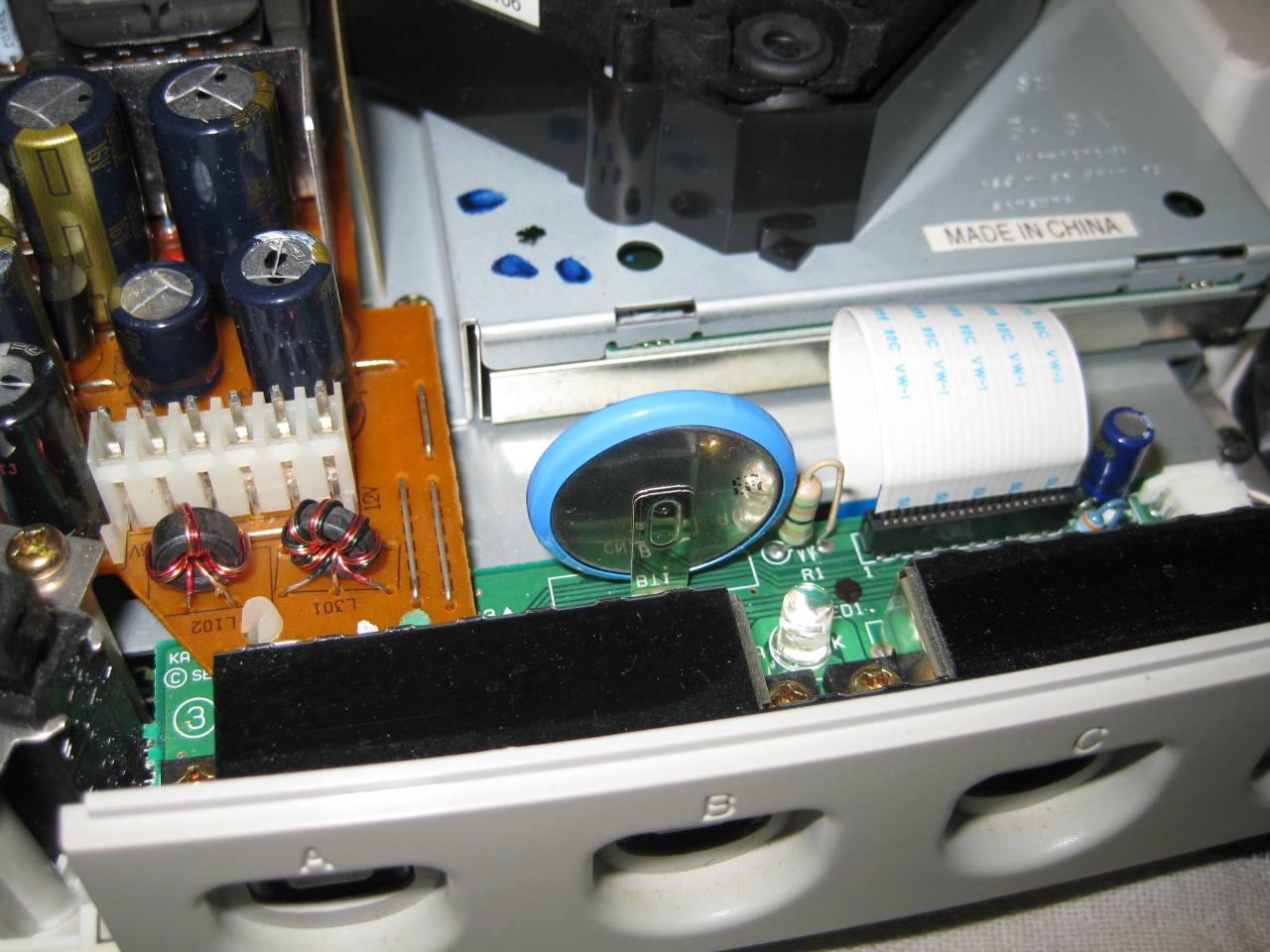
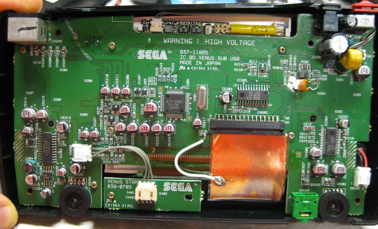
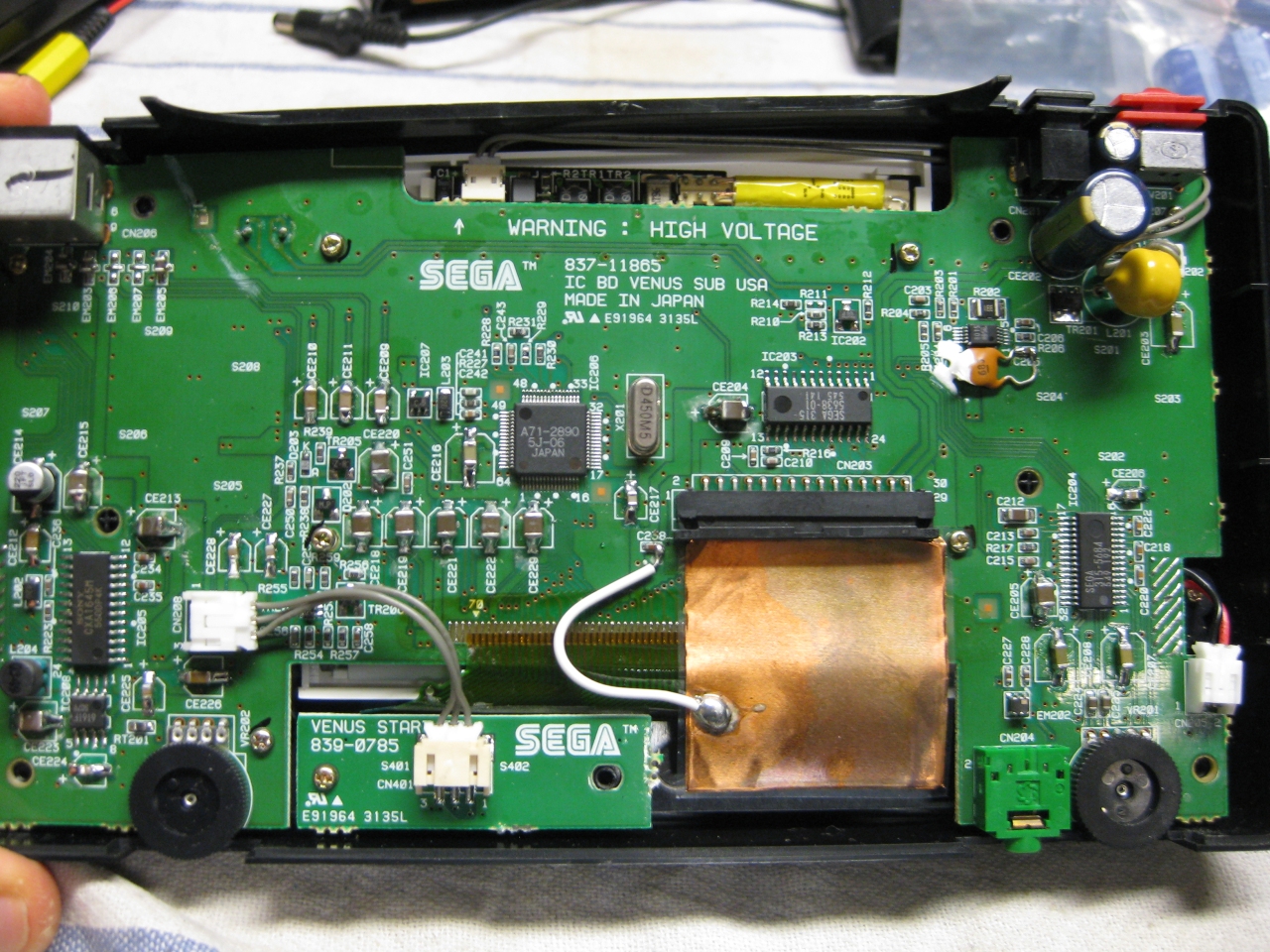
Now we have to take the 2nd Mainboard (CD-Area). We have to mod the Display with two Duo Leds. First you have to remove the shielding.
Desolder the Display Unit.
Remove the two original LEDs.
Use some tape and double sided adhesive tape
The Center of the 3 pins of the DUO-LED is GND. Solder both to the GND Area of the mainbord
(I used some fiberglas pencil)
make space for the legs of the LED at the PVC of the Disyplay
use four 220Ohm resistors and head shrink tube to avoide short curcuit.
Here you can see the routing of the 4 wires bounded with some tape.
Now it is time to get the „power“ over the reset button. It is placed on the CD-Mainboard. Lucky the Signal is going through the 36 Pin Connector on the left site.
You will have to cut pin 11 at the outersite of the connector.
PIC Pin 13 grey is connected to the upper site. Its for the Reset switch
PIC Pin 11 white is connected to the lower site (Reset Sega 315-5660 IC Pin 78)
Rom Part – for playing Cds around the world
You are in need of a Eprom (27c2004) and burn all 3 bios Version into it. The usa, japanese and pal Version. You can select the different Bios Version via A16 (Pin 38) and A17 (Pin 39) of the Eprom.
The order is: USA-> JPN -> EUR.
You can do it by yourself. Take the CD-Bios Versions and make a byteswap each of them.
The concat the 3 Files via Windows Commandline copy
The final goal is to get 2 wires from the 16F630 PIC to the Eprom.
Here we make use of 2 wires from the Sega Expansionport.
PIC 8 /Eprom 38
PIC 10 /Eprom 39
EUR
0
1
JPN
1
0
USA
0
0
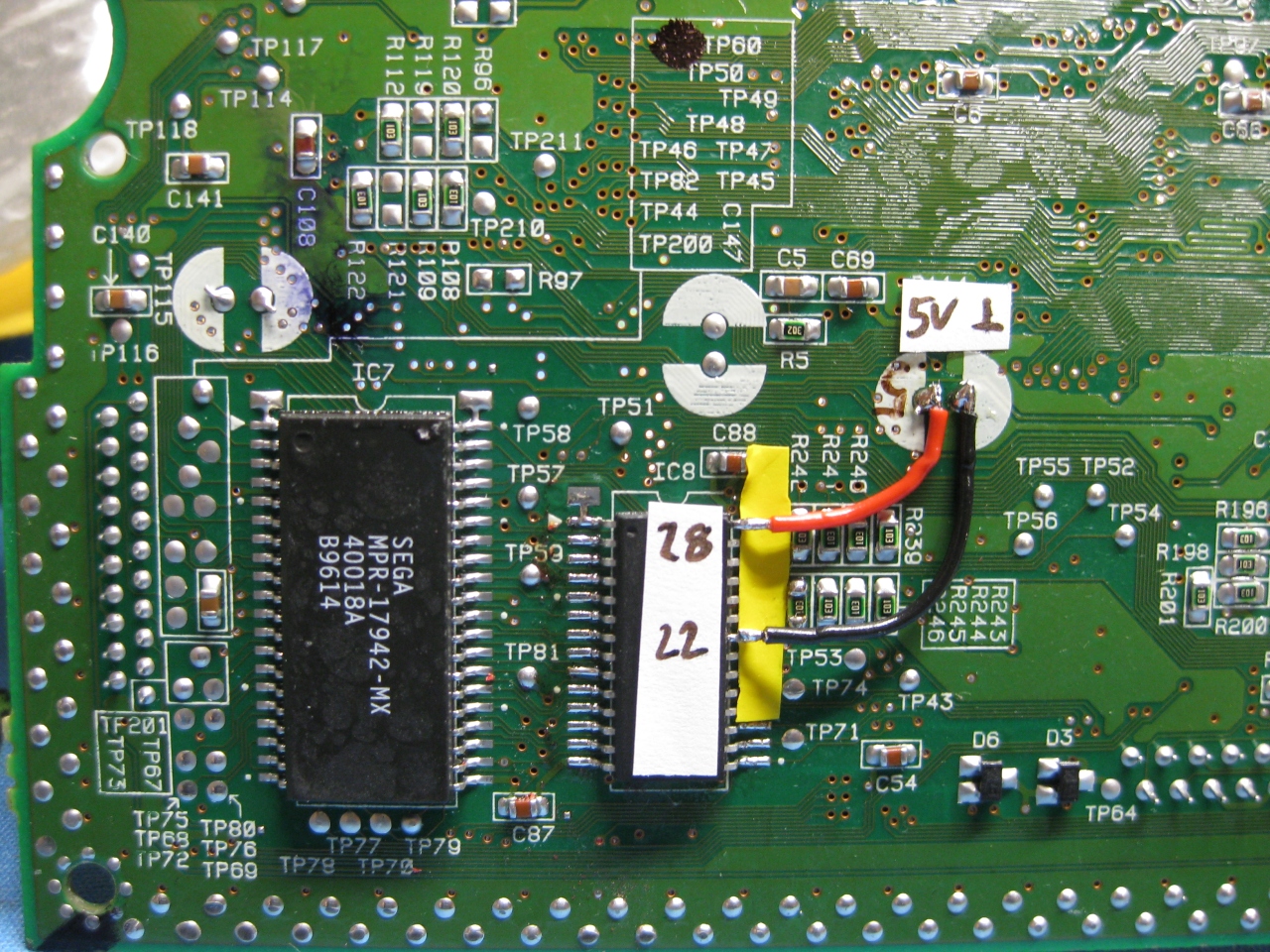
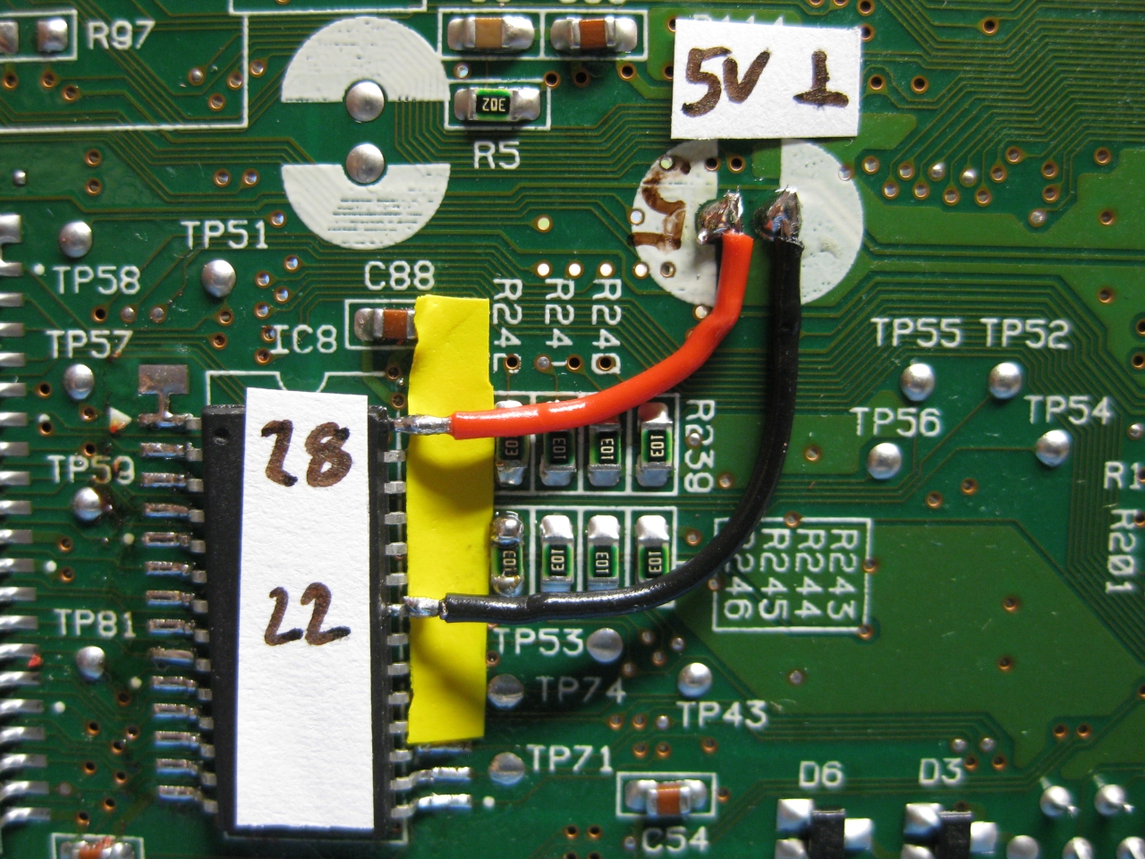
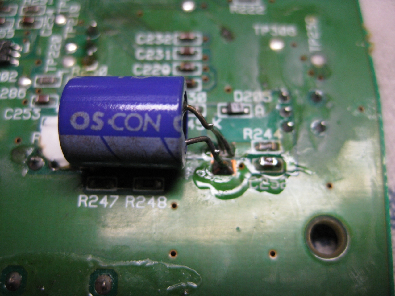
First you have to disable to onboard bios. Desolder PIN 2 (CS) of the onboard ROM and lift the pin up. Solder a red wire from the lifted Pin 2 of the ROM to Pin 40 (5V) of the ROM.
Now its time to prepare 38 wires each 5-6 cm and do some soldering 😉
Wire blue and yellow as you see on the picture. This to wires will do the Bios selection:
red and green coming from the 5mm Duo-Leds. Solder both parallel to PIN 5,6 of the PIC
Adding Sega 32X Support (optional)
The pink wire to the AV-Port is optional, only necassary for 32X support
You will have to cut the red marked circuit and solder a pink wire to Pin 6 of the AV Port
We will disable the Mono-Audio for this function. This will not be a problem, because STEREO-Audio is still working. (Who needs mono ?)
On the right picture you can see the right routing for the wire:
To prevent short circuits use tape on the left site of the CD-X.
Here you can see the routing of the LED wires.
Make sure no red/green wire is nearby or inbetween of the 36 PIN connector between the two mainboards:
Inspired from petes fabulous site www.mmmonkey.co.uk and his switchless mods,
I want to make the ultimative Sega Genesis 2 switchless MOD including 32X and Sega CD2.
In the beginning we have to mod the Genesis 2 with the switchless mod, like I done before.
(Thanks to SEB for the great PIC Code).
Difference between standard Sega Genesis switchless mod
For making a 32X working you are in need of the pink wire. This signal is needed in the 32X.
We can make use of the A/V connector cable between the Genesis 2 and the 32X. The Mono Audio Signal is not in use, so we can cut the original Mono signal at the Genesis 2 A/V connector and the 32X A/V connector.
Here you will see the Sega Genesis 2 switchlees mod including the 3 more wires (yellow, blue, and pink).
The Pink is needed for the 32x.
Blue and yellow is needed if you want to make a Sega CD working too.
For 32X support add a 2nd pink wire to Pin 12 of the PIC.
At the solder site you have to cut the cirquit path to Pin 6 of the A/V Port and solder the pink wire to Pin 6 of the A/V Port.
For Sega CD support you have to cut Pin A01 (yellow wire) and Pin A30 (blue wire) of the Genesis Expansionsport and solder the 2 wires to the PIC Pin 10 blue and PIC Pin 8 yellow.
Backsite of the Genesis 2:
Adding 32X support
First you have to open the 32X and remove the shielding.
The only protection of the 32X is the 50/60Hz settings. You will find it at the right site of the mainboard IC12 SEGA 315-5788.
You will find R43, if its a PAL 32X (Pin 32 to GND) -> 50Hz
You will find R42, if its a NTSC 32X (Pin 32 to 5V) -> 60Hz
Remove the Resistor
Sega Genesis 2 A/V Pinout
Pin
Description
1
Blue
2
+5V DC
3
Green
4
Composite Video
5
Sync
6
Audio Mono
7
Red
8
Audio Stereo L
9
Audio Stereo R
On the solder site you will have to Cut the cirquit path to Pin 6 of the A/V Port.
Solder one pink wire from AV Out Pin 6 (solder Site) to Pin 32 of IC12 (component site)
Adding Sega CD 2 support
You are in need of a Eprom (27c2004) and burn all 3 bios Version into it. The usa, japanese and pal Version. You can select the different Bios Version via A16 (Pin 38) and A17 (Pin 39) of the Eprom.
The order is: USA-> JPN -> EUR.
You can do it by yourself. Take the CD-Bios Versions and make a byteswap each of them.
The concat the 3 Files via Windows Commandline copy
The final goal is to get 2 wires from the 16F630 PIC to the Eprom.
Here we make use of 2 wires from the Sega Expansionport.
Pin8 yellow 16F630->Exp Port Pin A01@Genesis 2->Exp. Port Pin A30@SegaCD2->Pin 38Eprom
Pin 10 blue 16F630->Exp Port Pin A30@Genesis 2->Exp. Port Pin A30@SegaCD2->Pin 39Eprom
Pin A01 and A30 of the Expansionsport carrying GND. There are many ground Signals at the Expansionsport. So we can cut these two of and make use of the free Pins for the Bios select.
PIC 8 /Eprom 38
PIC 10 /Eprom 39
EUR
0
1
JPN
1
0
USA
0
0
First you have to remove the original Bios:
cut the 2 wires left and right (A30, A01)
You will have to pullup Pin 38 and Pin 39 of the Eprom and wire blue and yellow like the following picture
Here you can see the complete eprom attached
Look here for a video showing how the modification is working (german language)