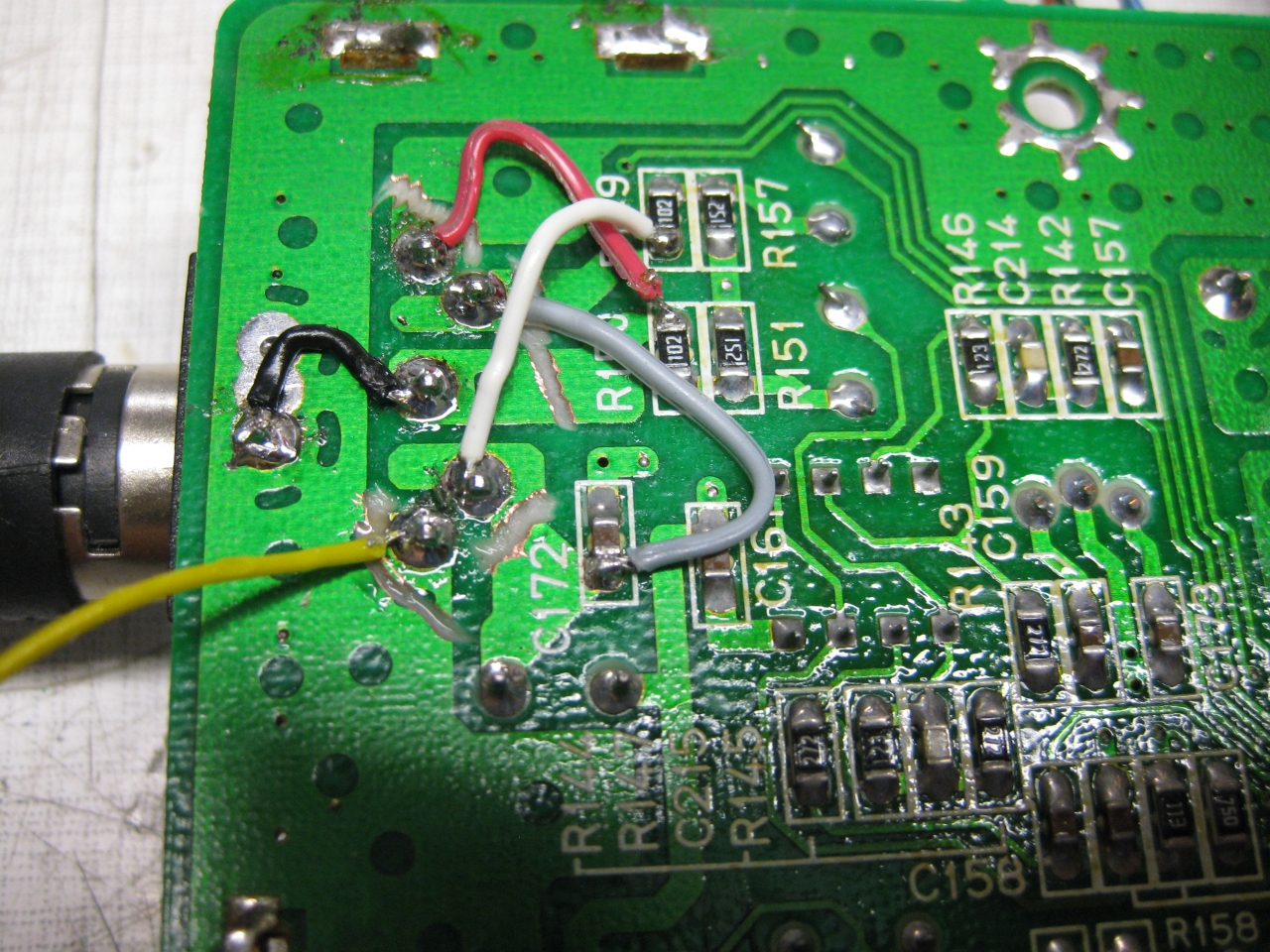
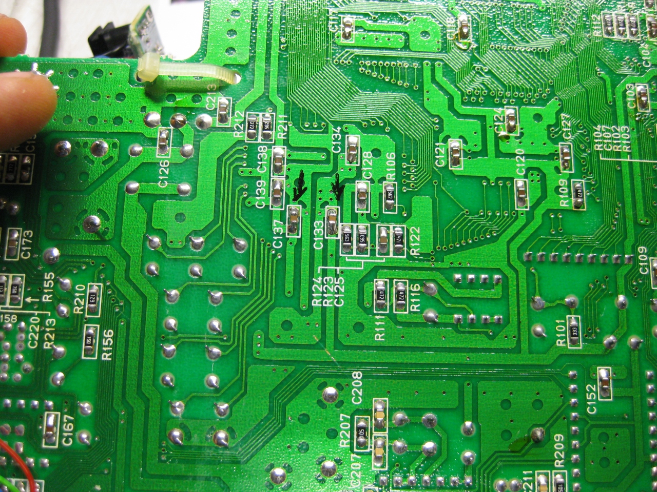
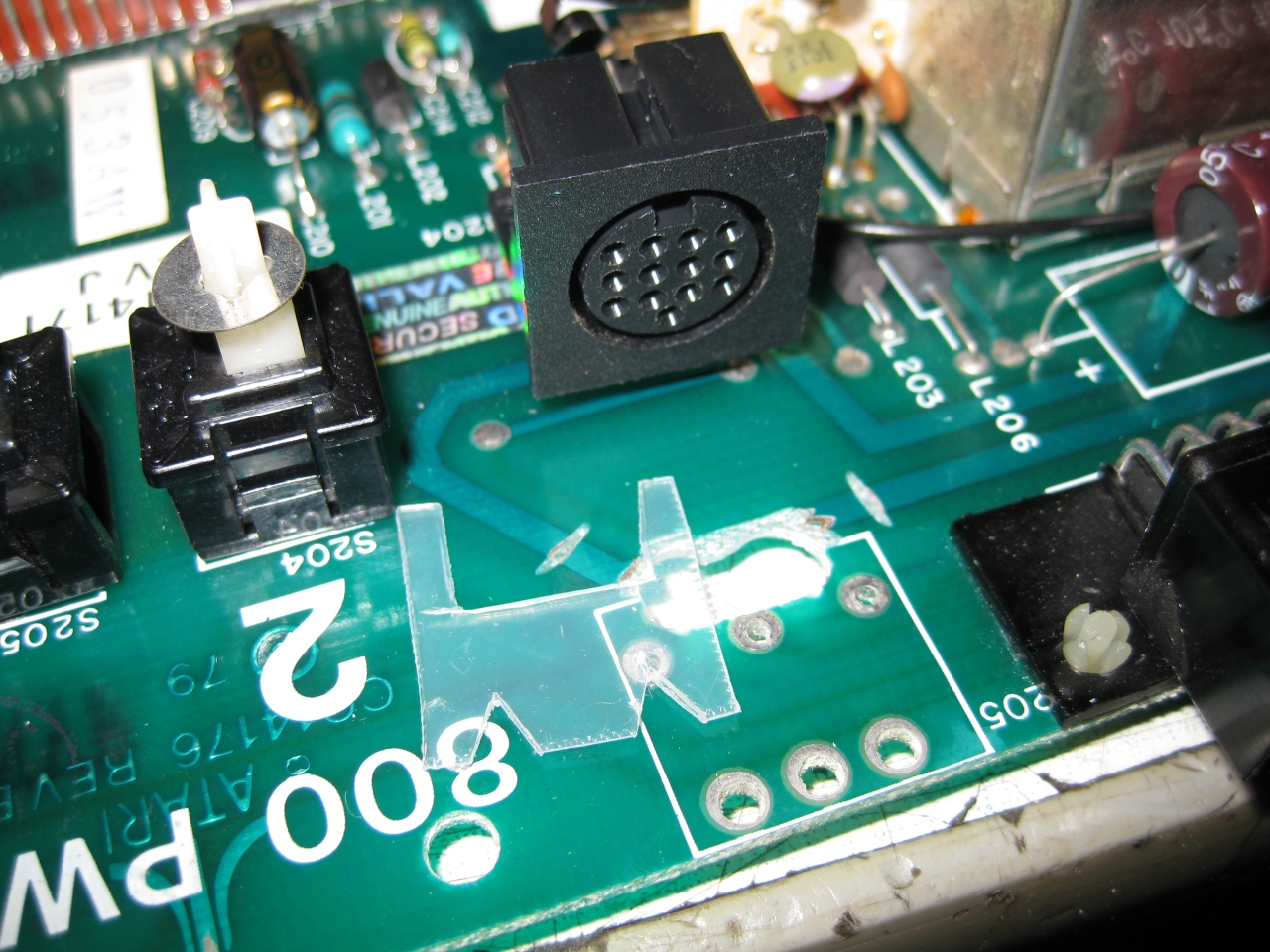
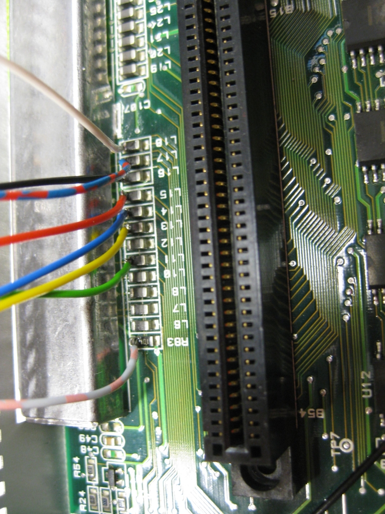
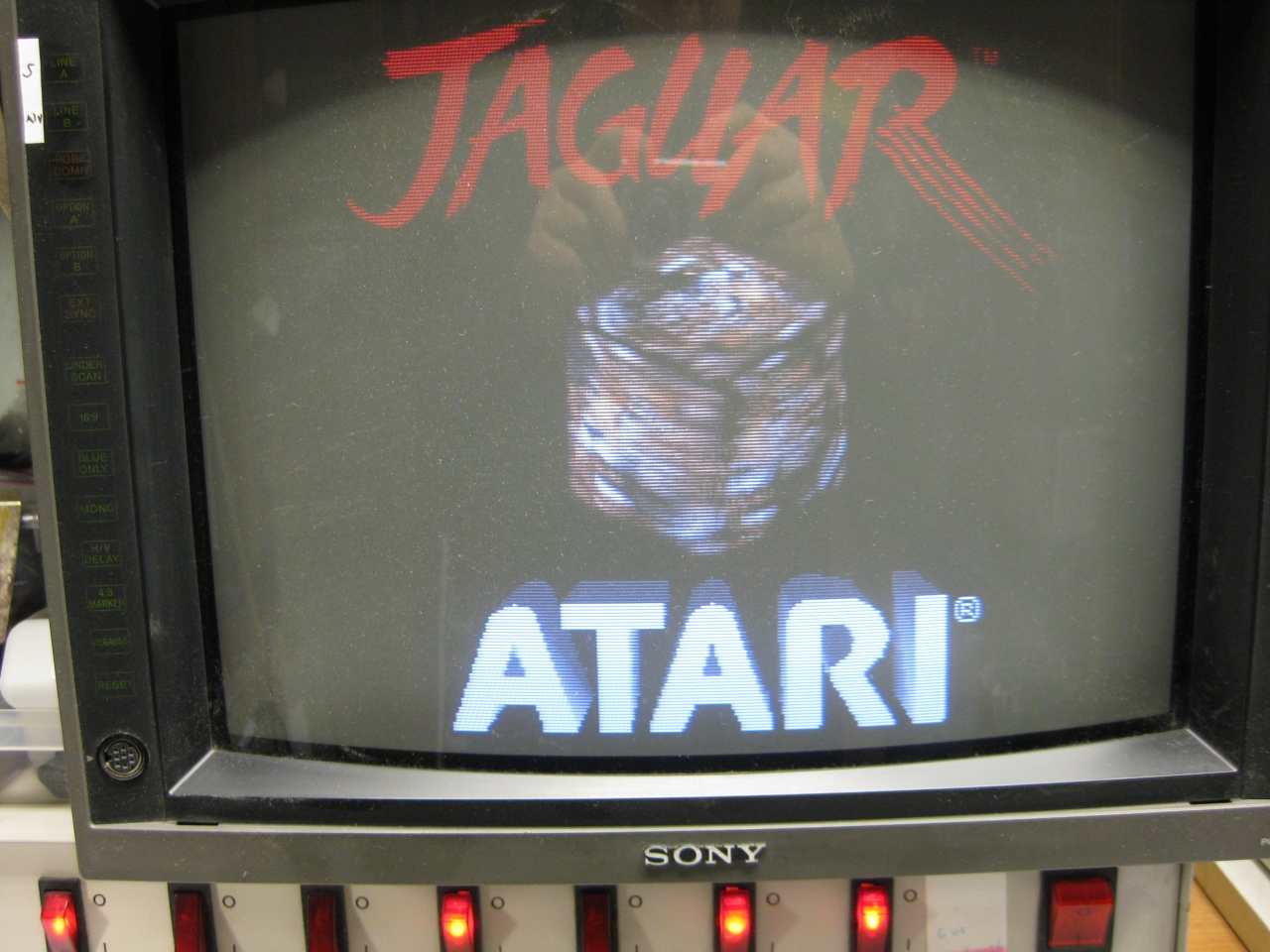
Atari 800 was my first computer after Sinclair ZX81 and its time to make the picture better. After checking the A/V Out it contains Video and S-Video in a good qualitiy. So i decided to replace the original DIN Connector and replace it with a DIN 13 like used in Atari 7800 french and Atari ST. I used some not needed pins from the Din 13 to put in Video and S-Video too. So its possible to use RGB-Output via a standard french Atari 7800 RGB Cable and with a special Cable made I can use Video and S-Video too via the same connector.
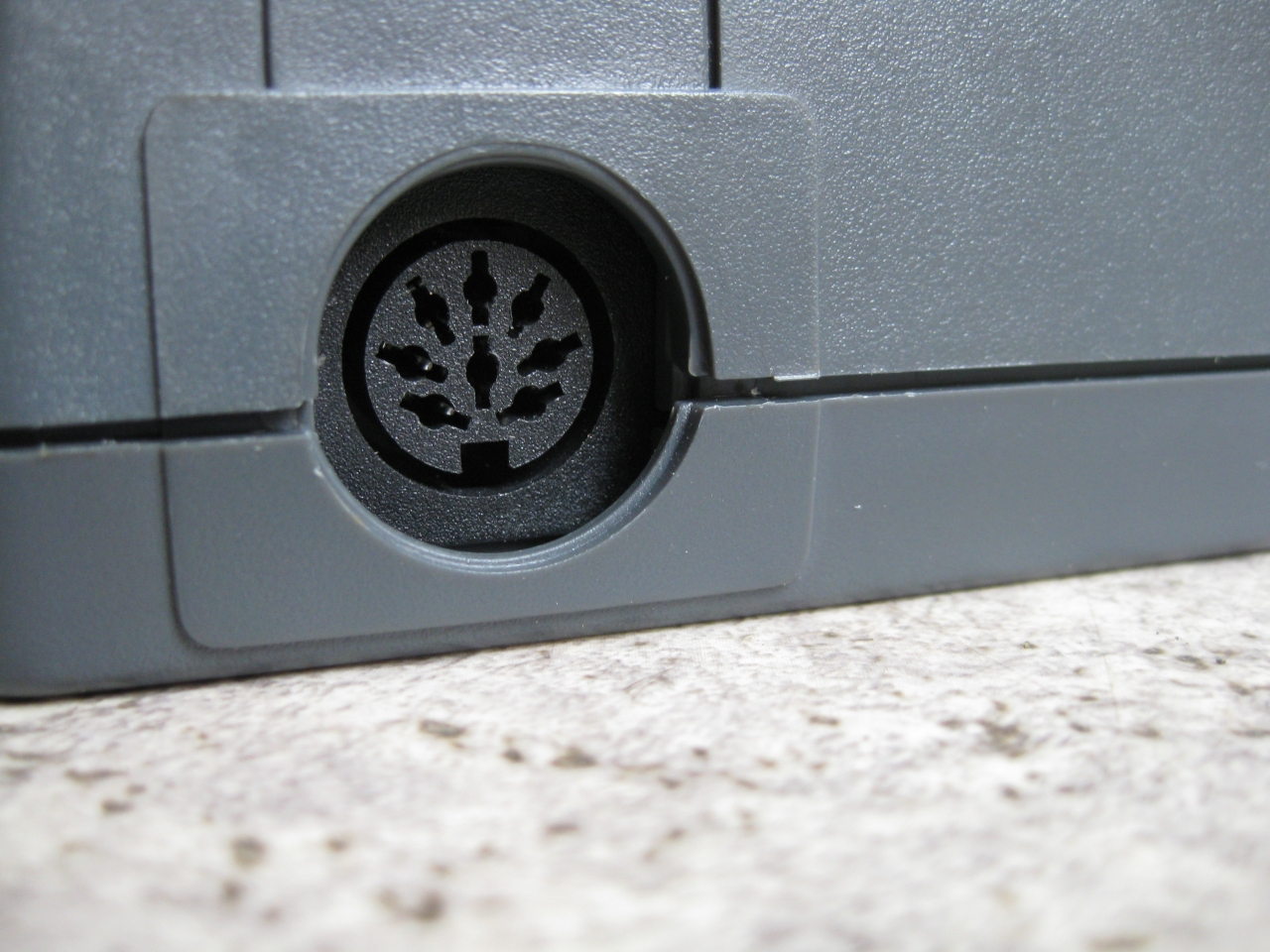
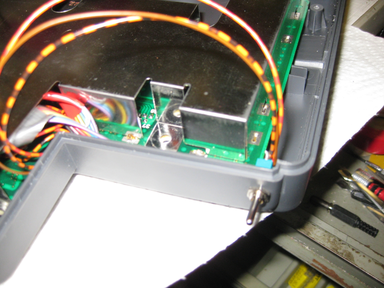
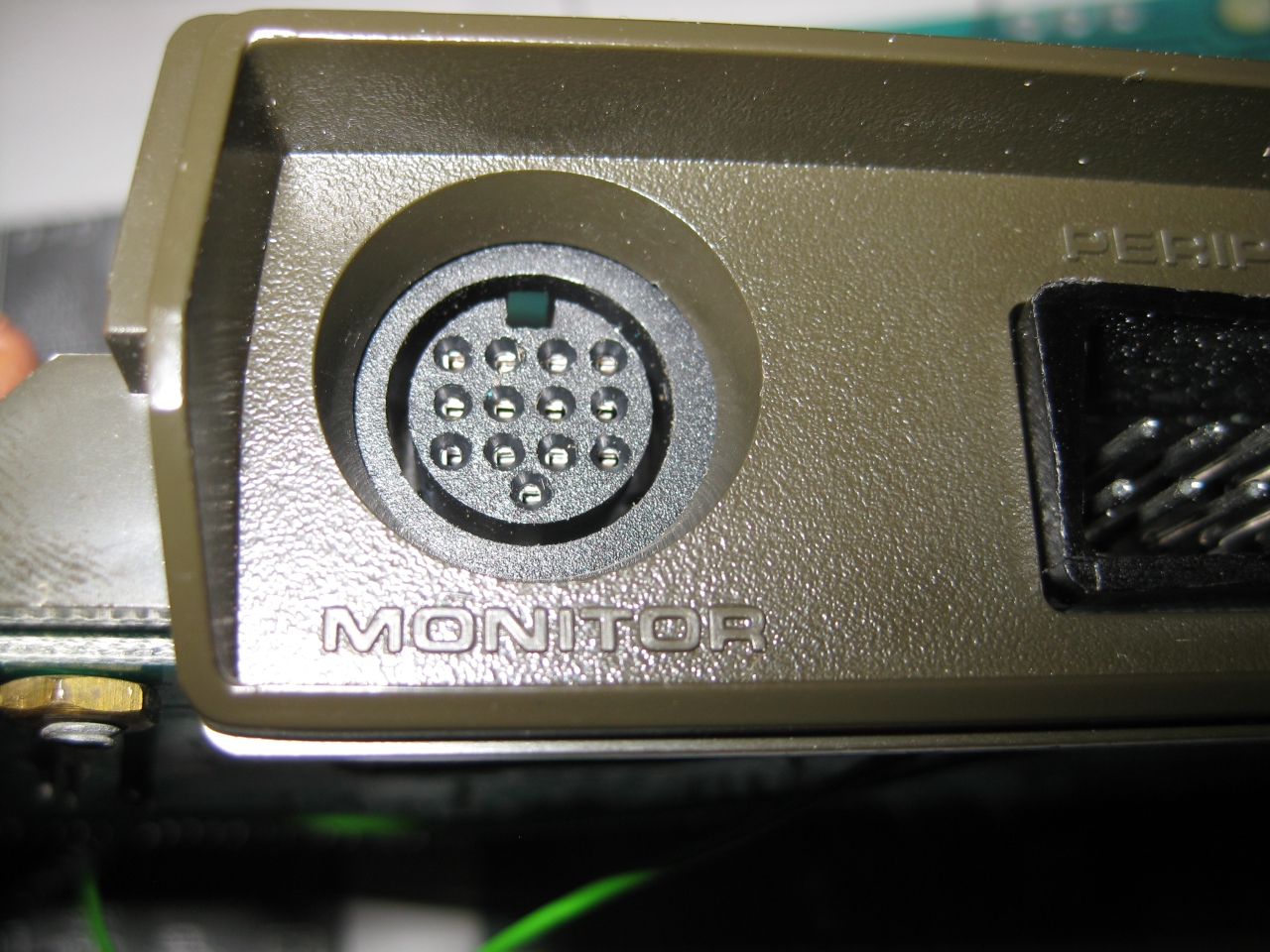
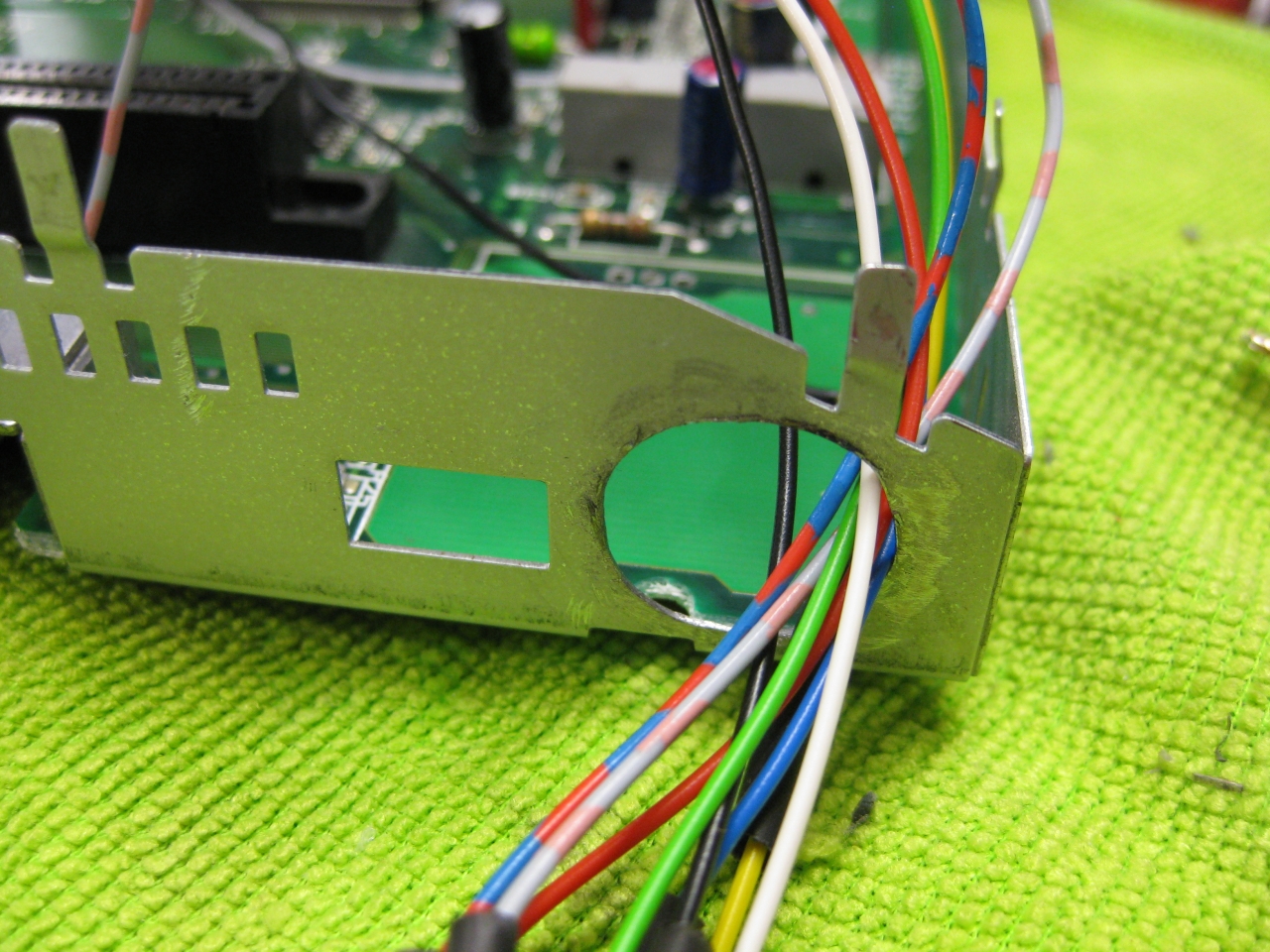
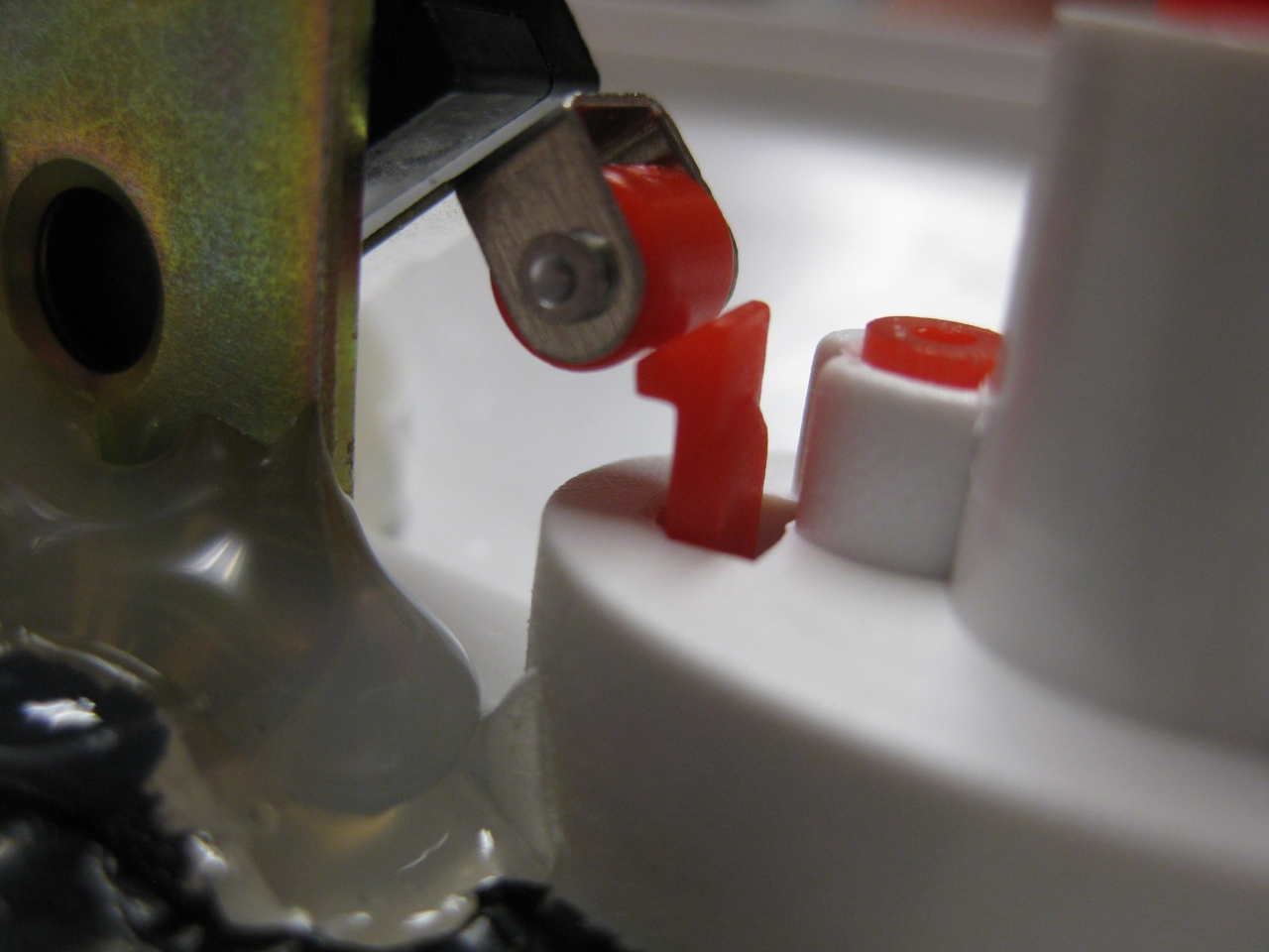
To put the DIN 13 in the right position i need some plastic and drilled holes downunder to make the Din connectors accessable
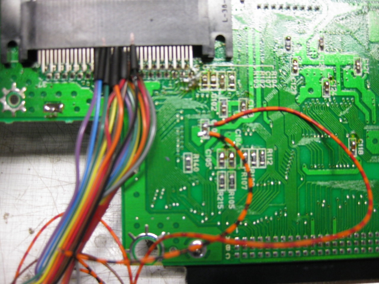
replaced DIN 5 to DIN13
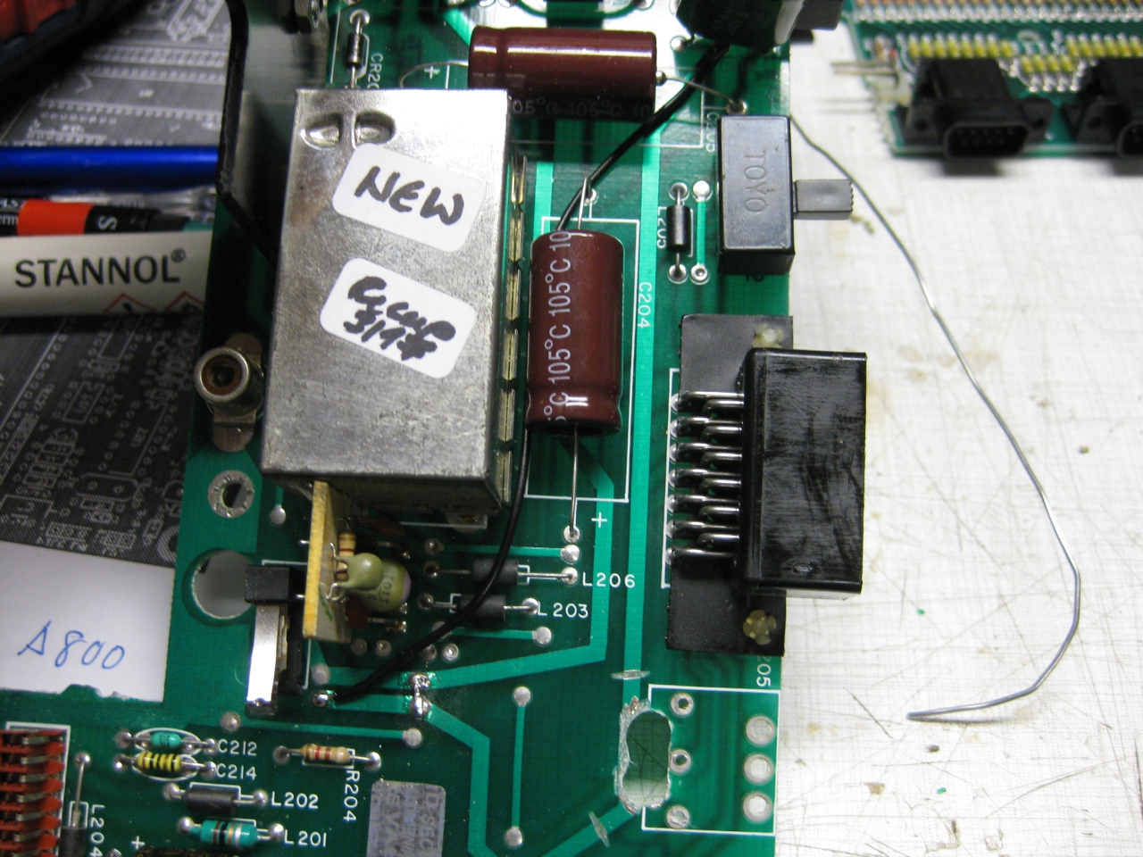
downunder chaos
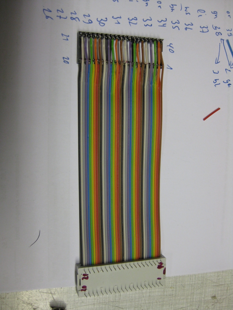
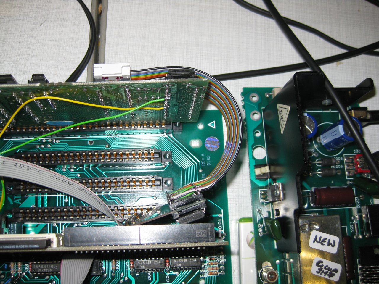
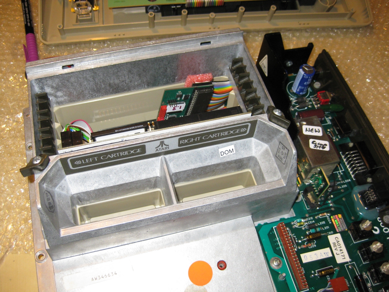
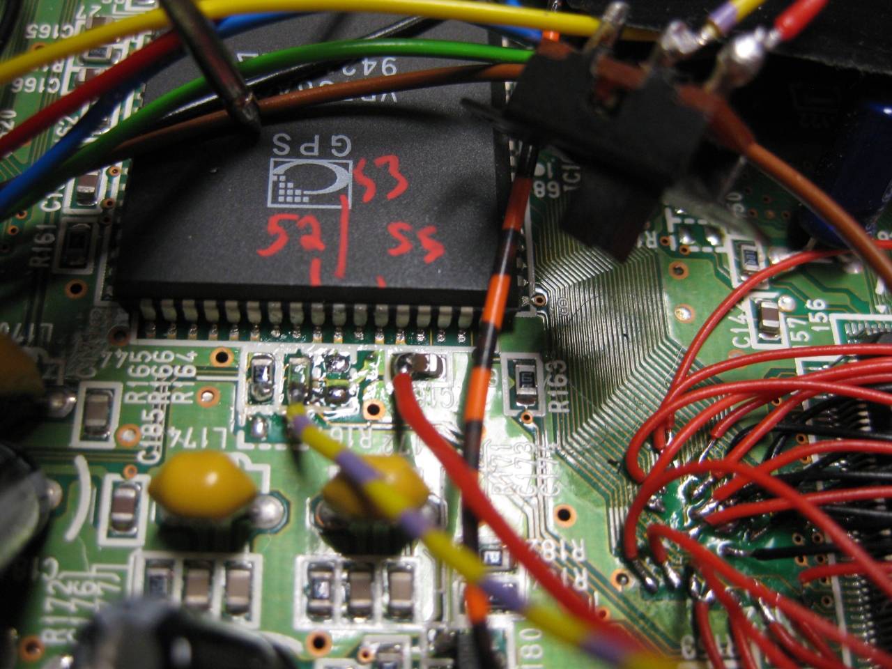
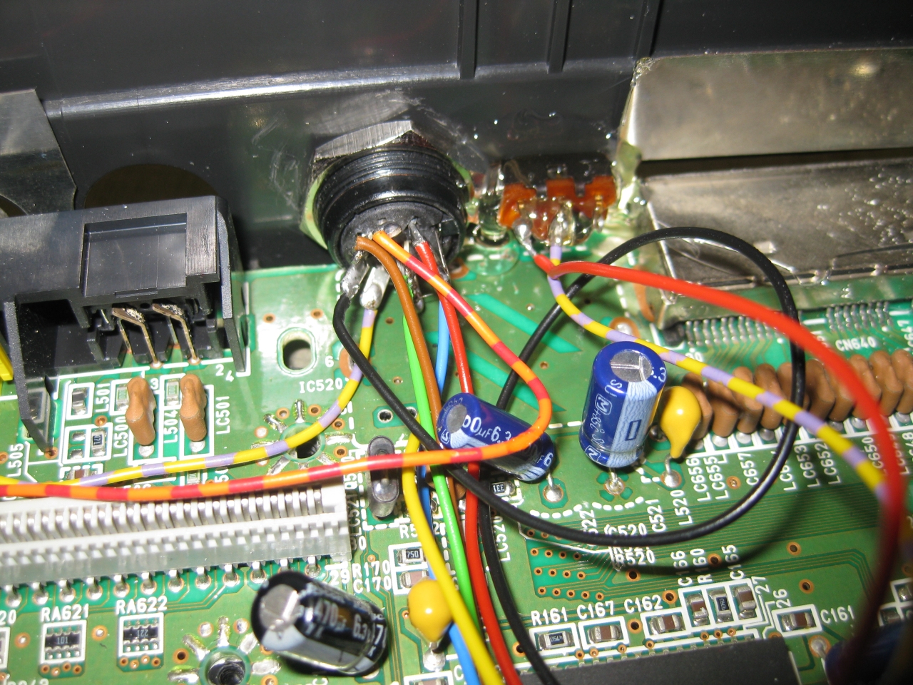
because of no space at the CPU Board I needed to move the Sophia Board to another place. I uses some ribbon extension like this
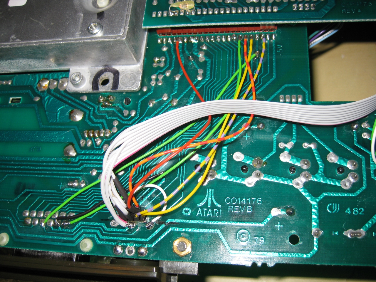
and here we go. In front you see incognito board too 🙂
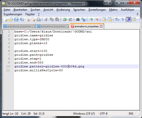
Here you will find a package including one demofile. gridlee You only have to change variable base to your path were the package extracted
To do some animations for goDMD you have to use mame. I am using groovymame, because it can be set to output native pixel resolution of the games. So you will get a pixelperfect output for the goDMD.
start mame via commandline: groovymame -mngwrite griddle.mng griddle and do some gaming. After exit you will find a griddle.mng.
To split the griddle.mng into pictures I used a programm advmng
start it in the path where the griddle.mng via commandline: advmng.exe -x griddle.mng
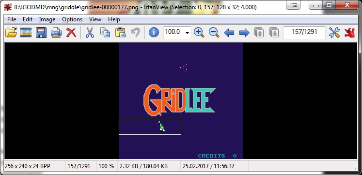
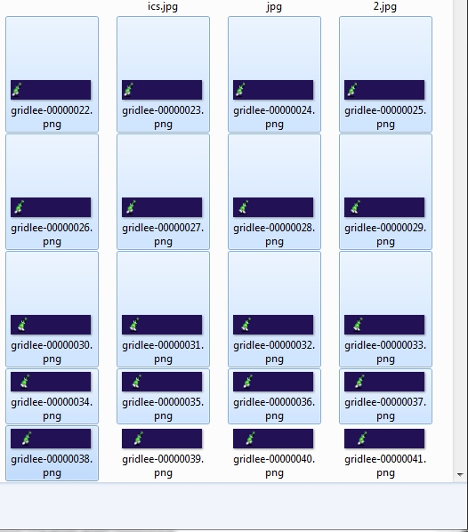
After this you will get a lot of pictures like: gridlee-00000022.png (Resolution: 245×240)
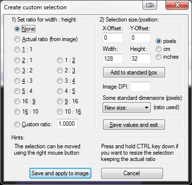
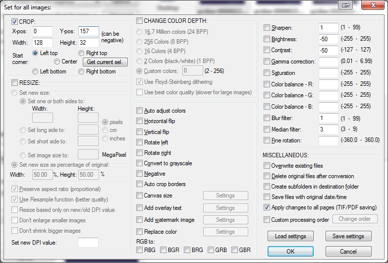
With the help of irfanview (a pictureviewer) you can create a custom selection (under edit) with Width: 128 and Height: 32.
After Pressing the Button: Save and apply to image you will see a window on top of the left png.
Move it with the help of arrowkeys to the area of interest
In Top Line you see (Selection: 0,0) this marks the X,Y Position. You have to enter these values in
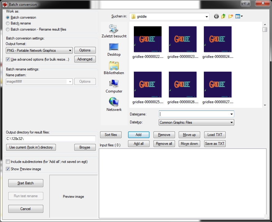
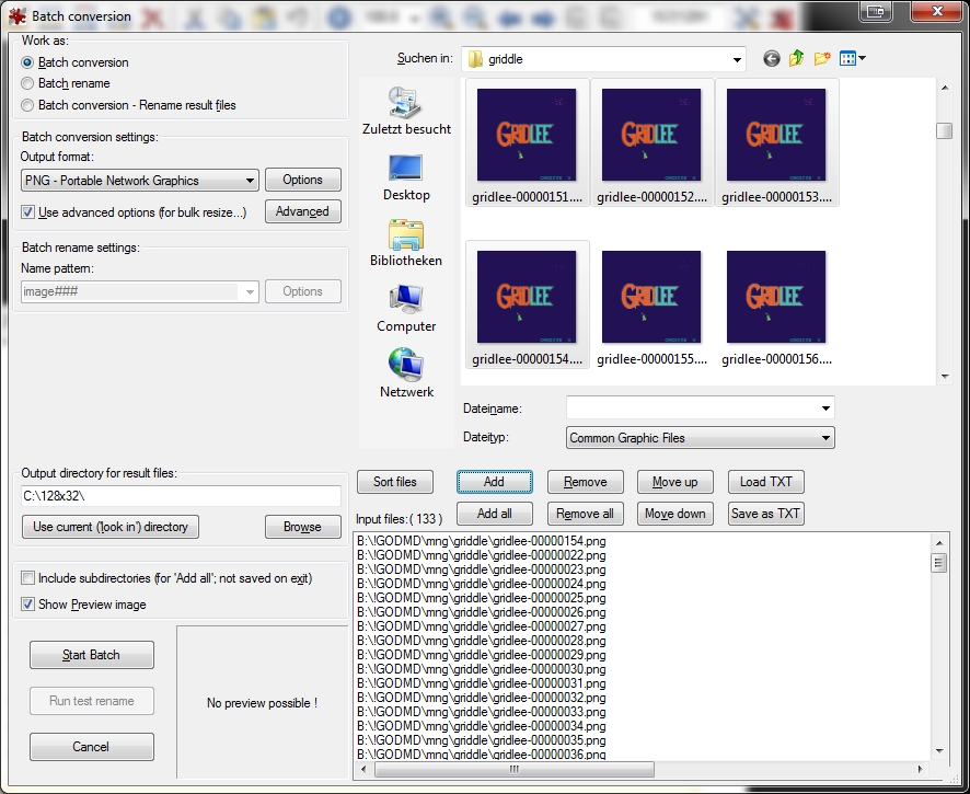
Under File: Batch conversion (set to PNG Output Format) and press Advanced Button: Here you can set the X-pos, Y-pos Position
Mark the amount of png you want to crop and add them
Start Batch
now you have a lot of cutted pictures in the right resolution
now put a animaions.properties in this folder
After this try to import it in the pin2dmd editor under animations: Load Animations
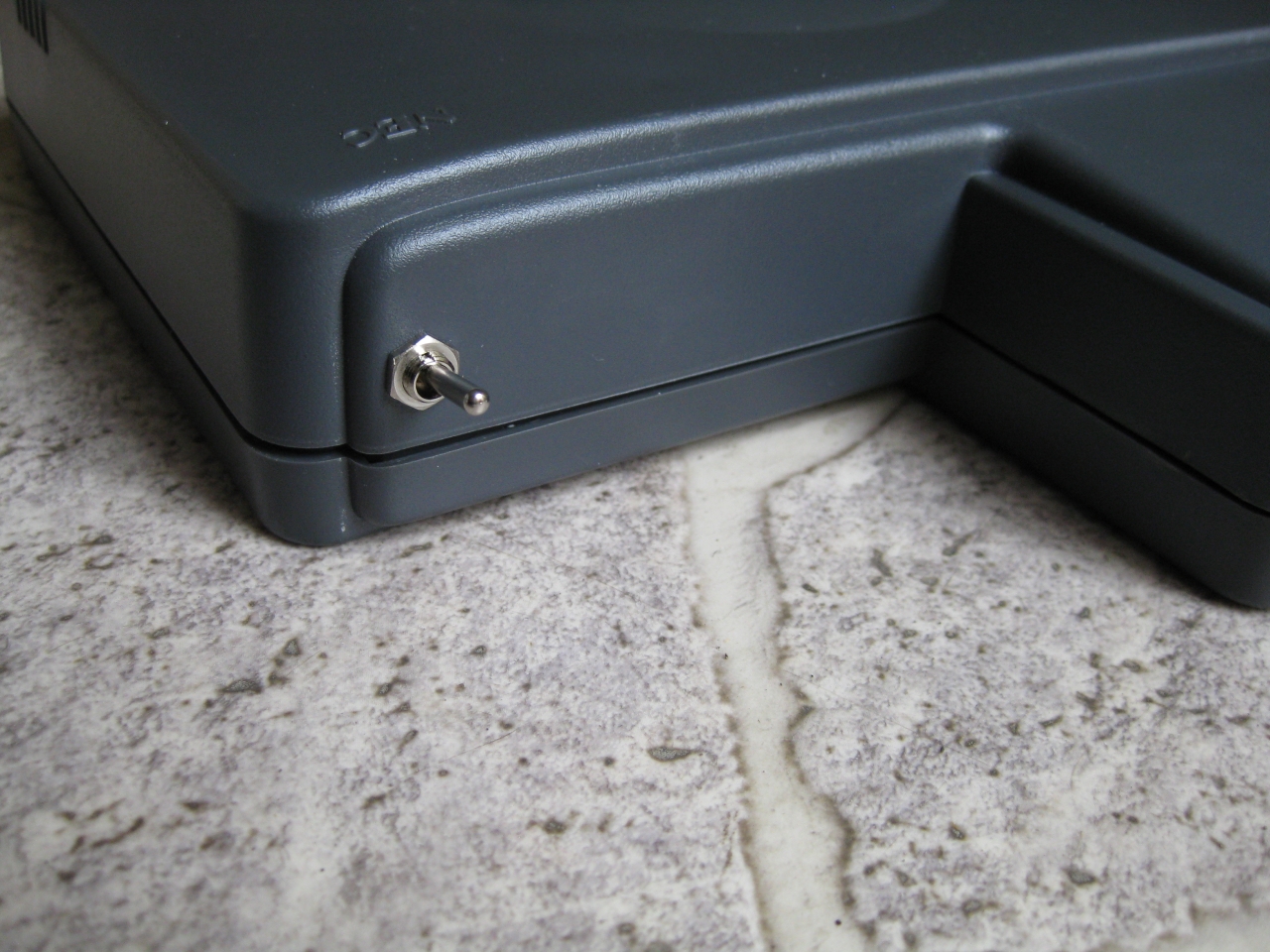
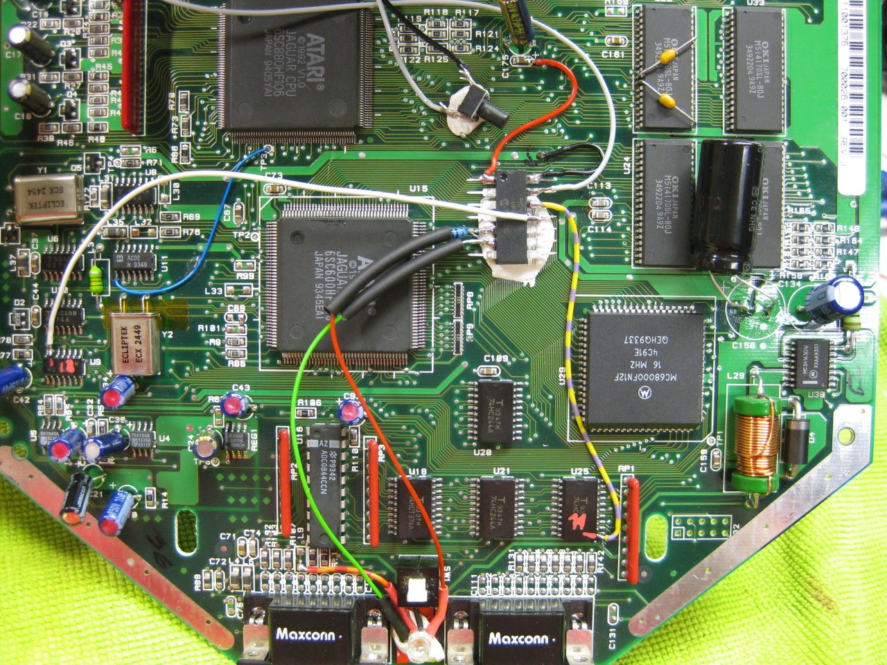
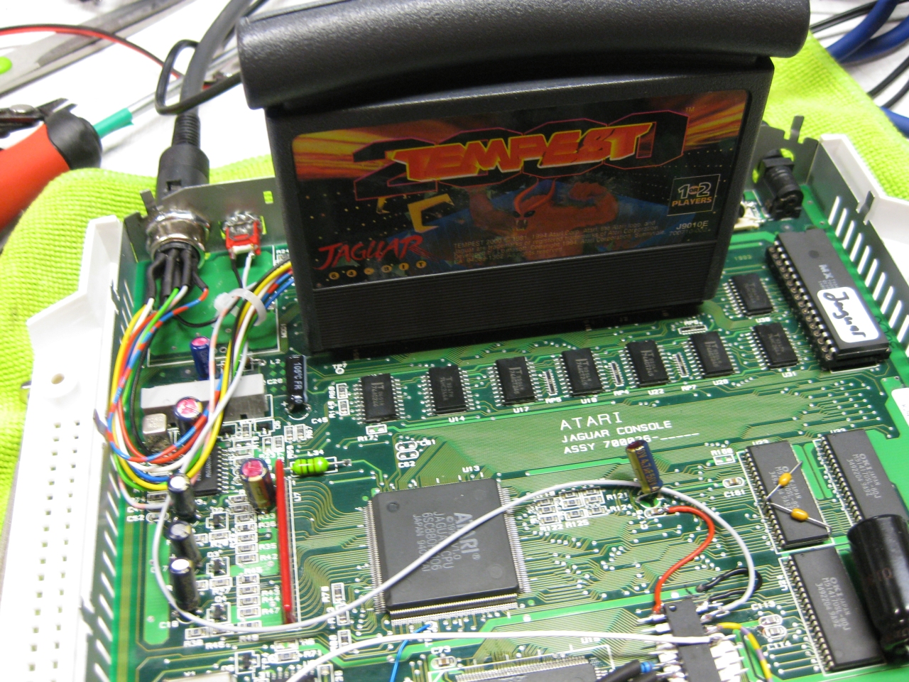
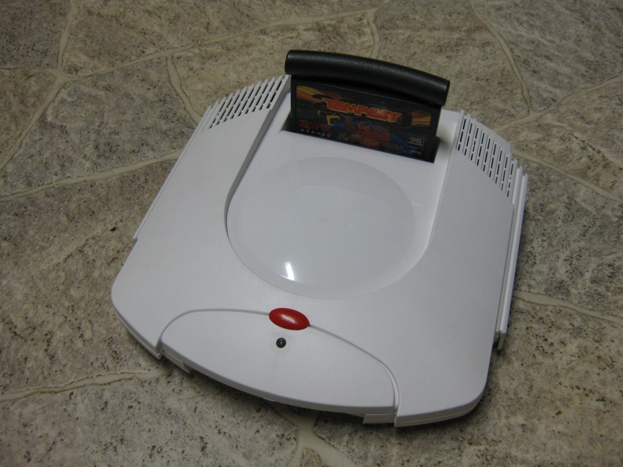
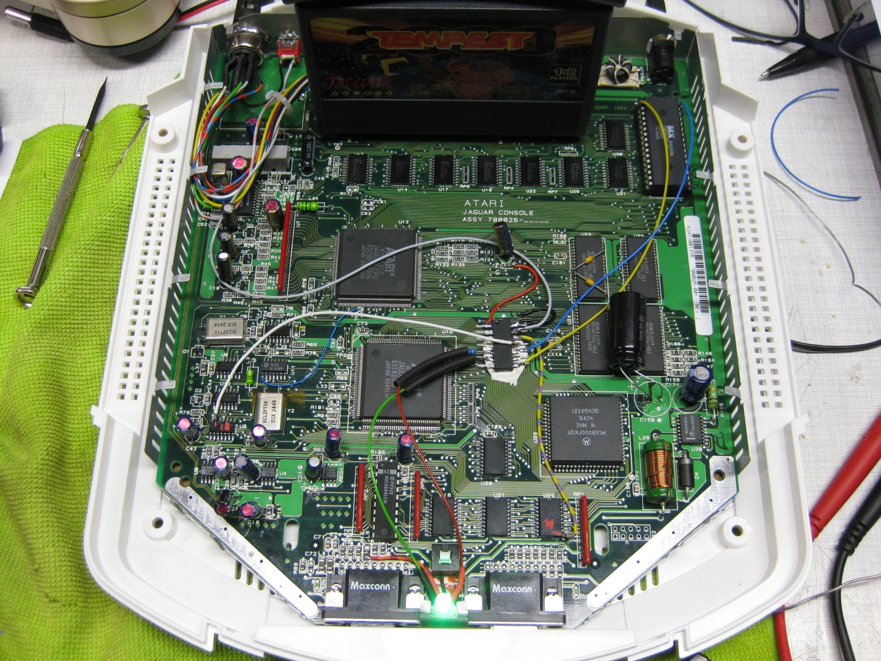
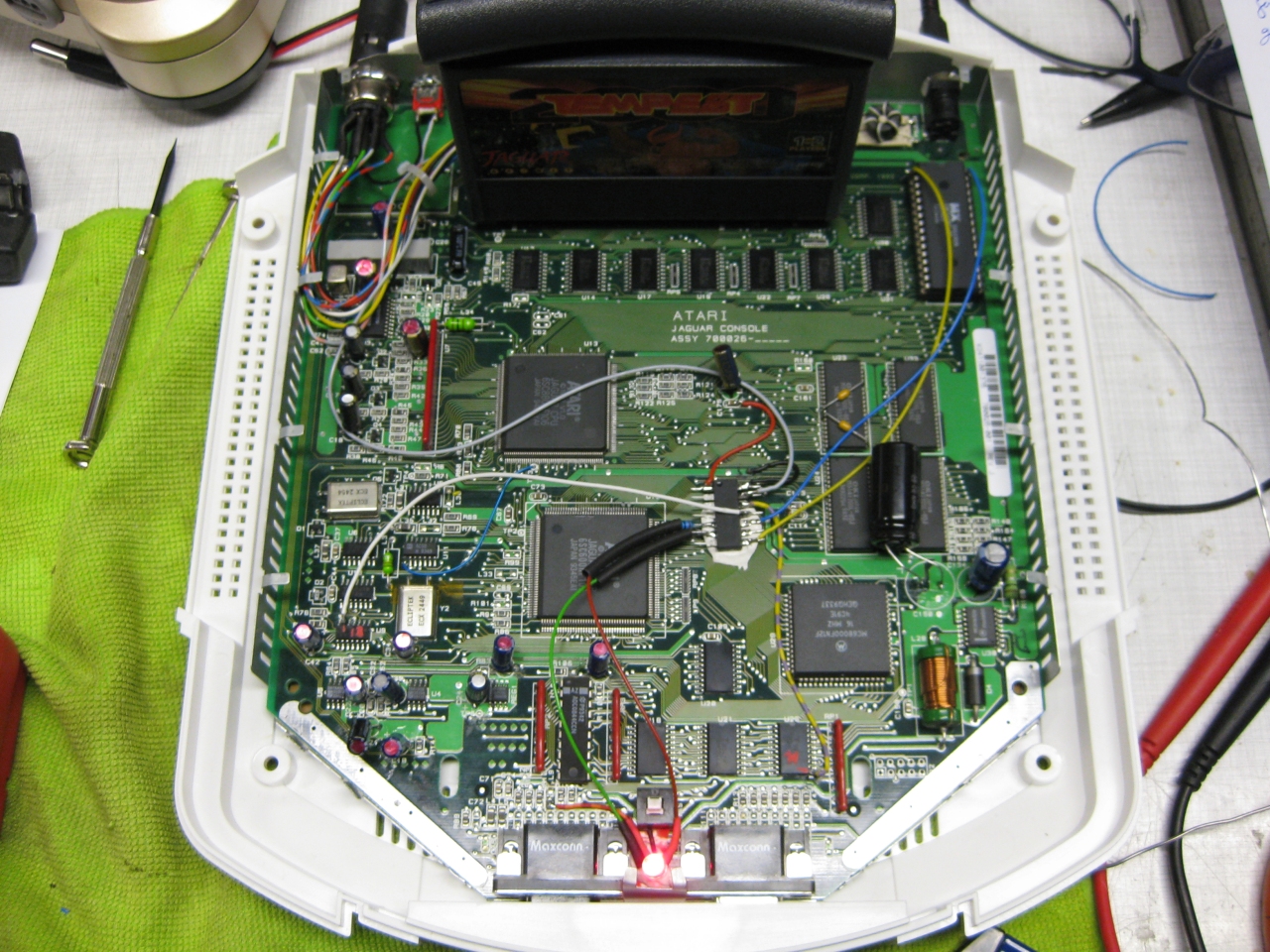
I got a white „dental“ case and its time to make the jaguar ready for 2017 😉
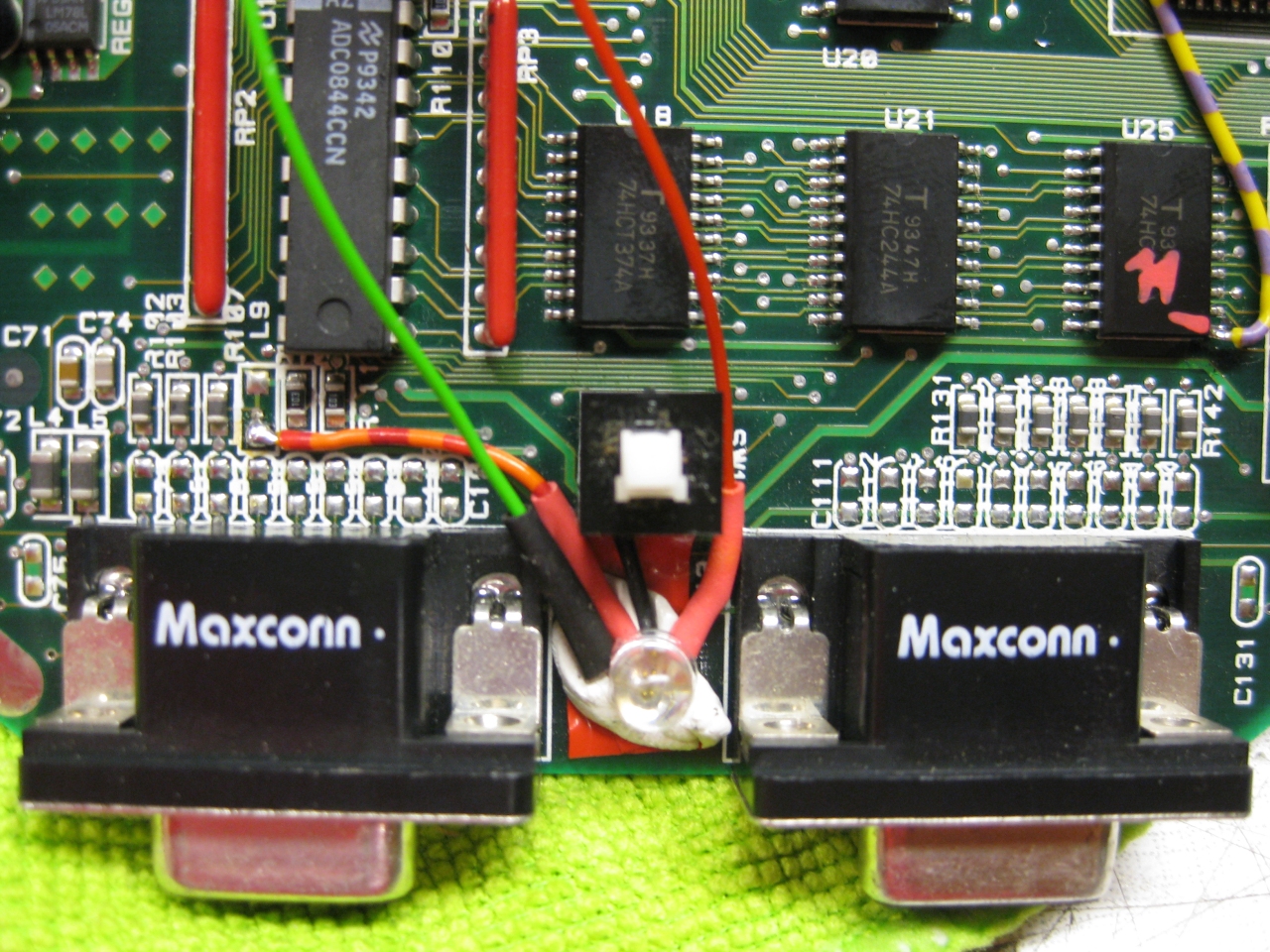
The title is something strange, but its comming from a Sega Saturn Mod years ago (the code is based on this). The Saturn reset button is used for change region and 50/60Hz.
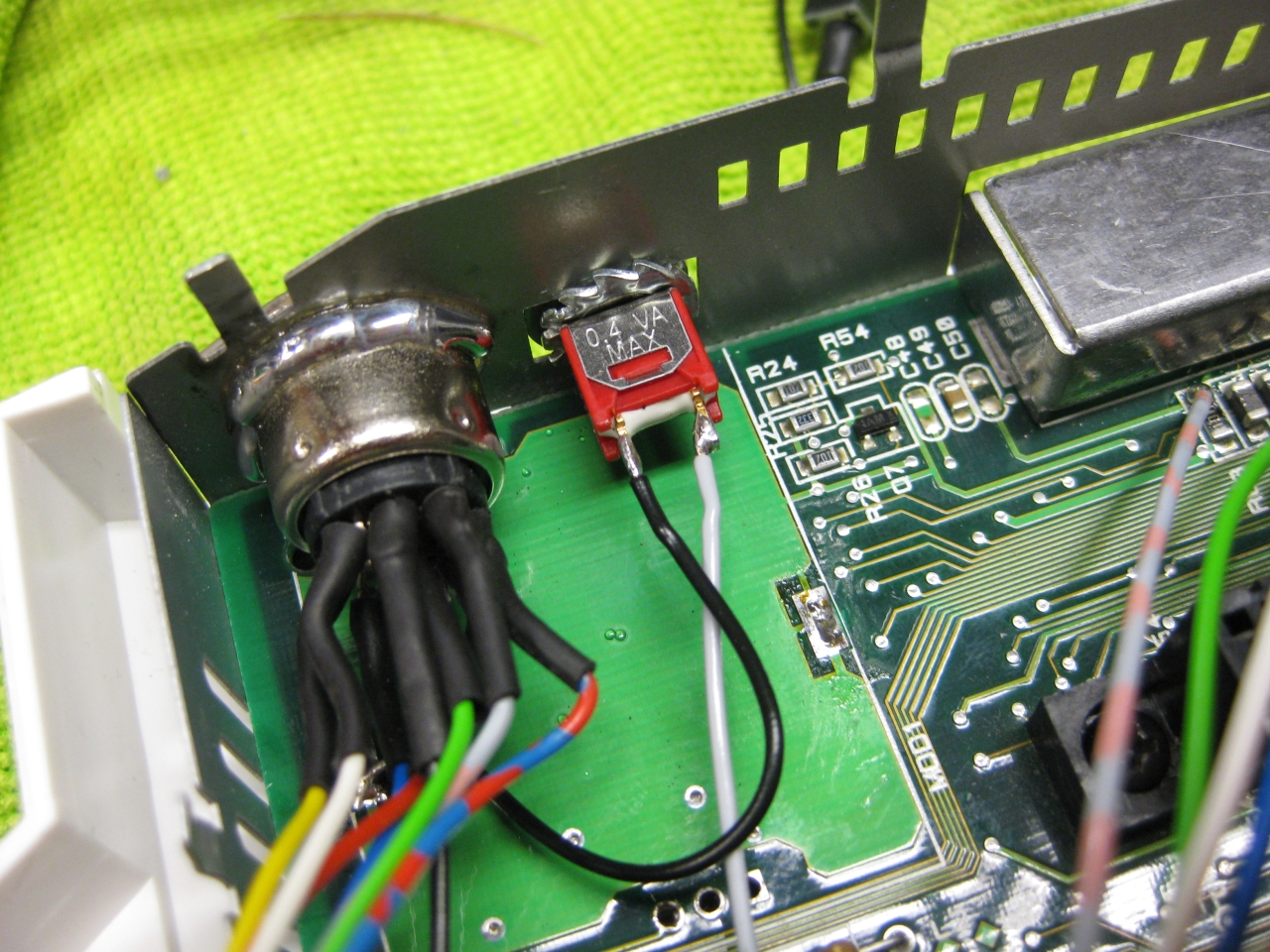
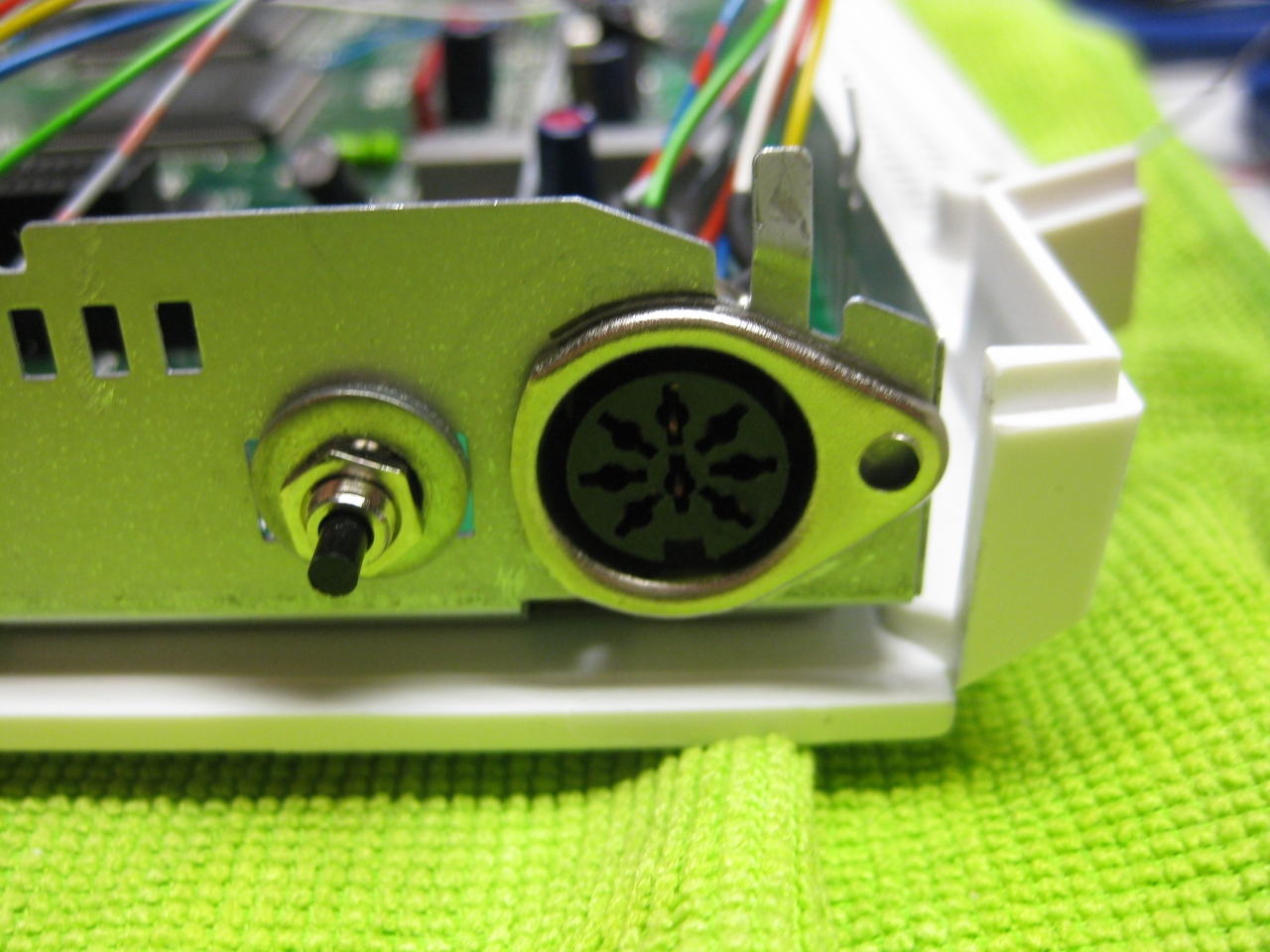
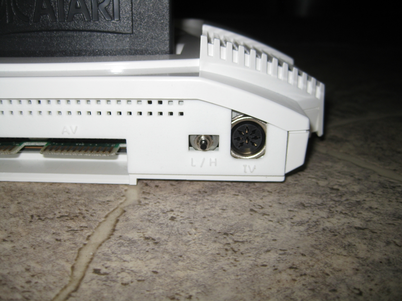
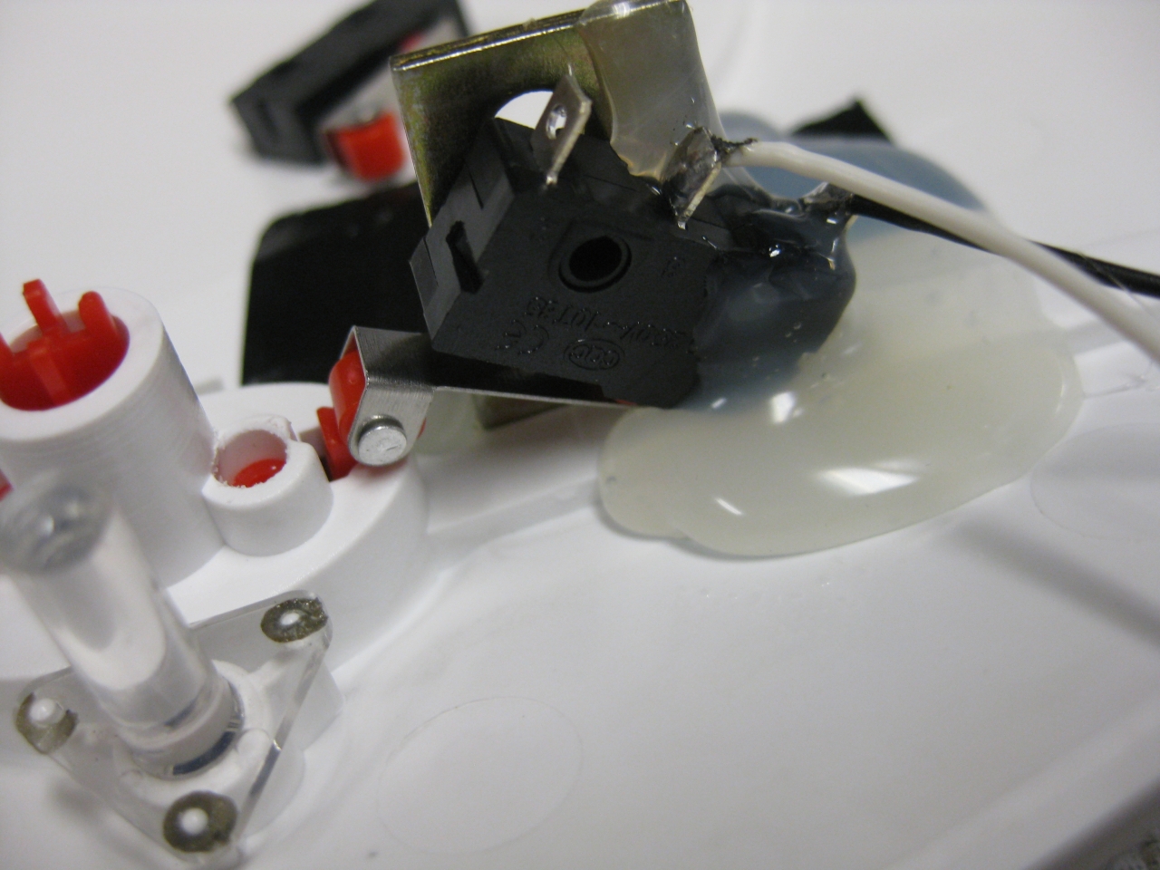
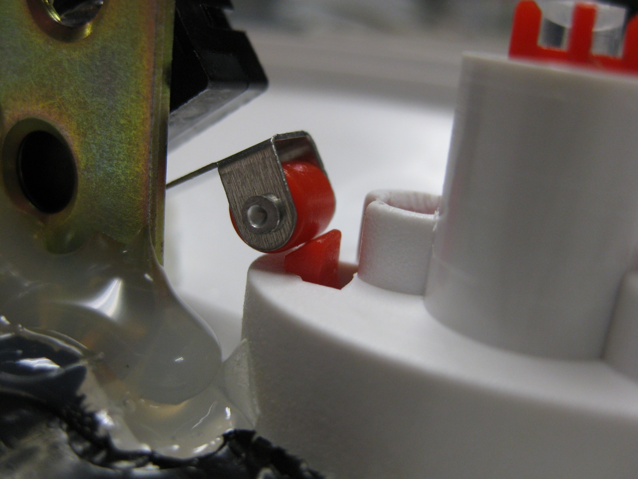
I removed the RF-Unit to put my „standard“ DIN Connector and for adding a button instead of the chanel selector. With the help of this tiny button you can select between 50/60Hz.
(Overview)
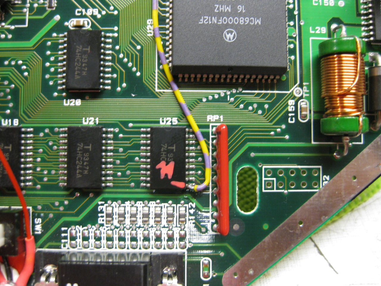
(U25 Pin 11 sets the Console between 50 Hz (GND) and 60Hz (5V)
I used a US 60Hz Jaguar for modding, so you have only to solder this wire to Pin 11
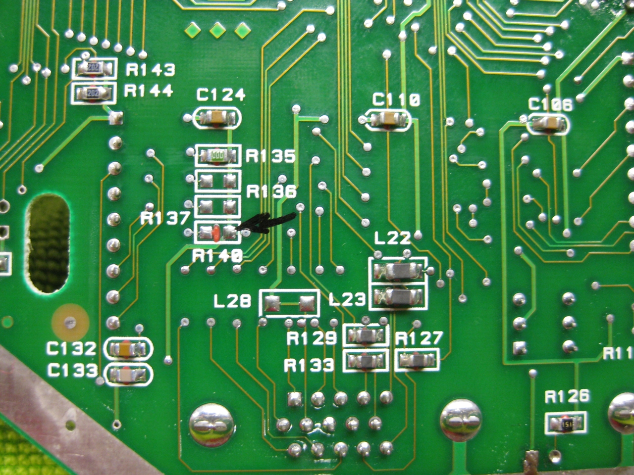
Attention If you use the PAL console you have to look downunder and remove a Resistor R140!
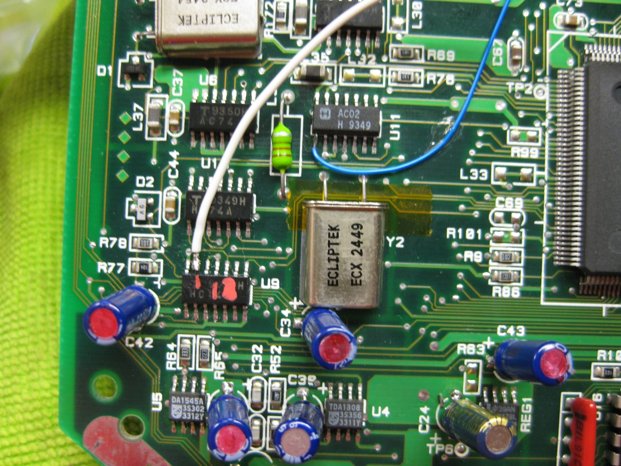
(The Reset Line you will find U9 Pin 13 (GND = reset)
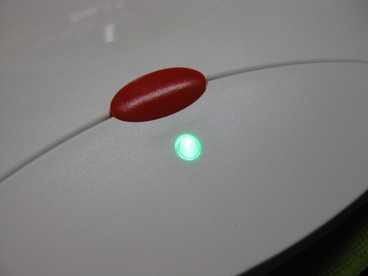
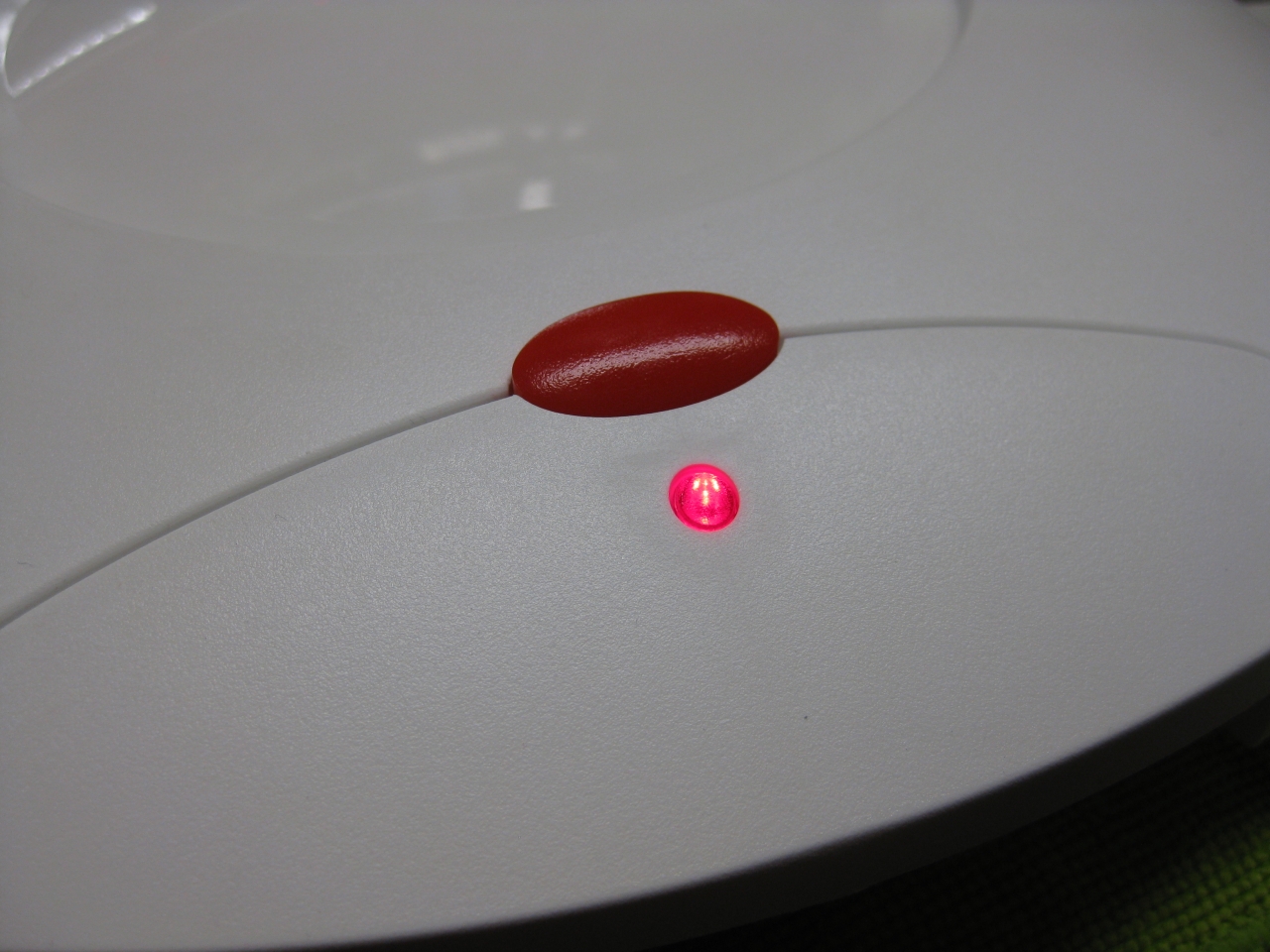
I removed the original LED and put instead a RGB-Led.
I set red for 60Hz and green for 50Hz.
If you find blue better, no problemo. But red/gn are the real colors of the Jaguar used in their countrys.
Usage:
Its like the switchless Mod for the Sega Saturn.
a) When you push the button for a moment. The Jaguar will do a reset
b) you push and hold the button. Now the Color of the LED will toogle between green and red. When you release the button
at red -> Jaguar Resets and starts with 60Hz
at green -> Jaguar Resets and starts with 50Hz
(bigger hole for Din RGB-Connector)
(RGB-Pinout)
(Reset button)
(overview)
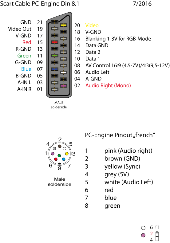
(my standard Din Pinout, based on modified 5 Pin Din PC-Engine + 3 more for RGB)
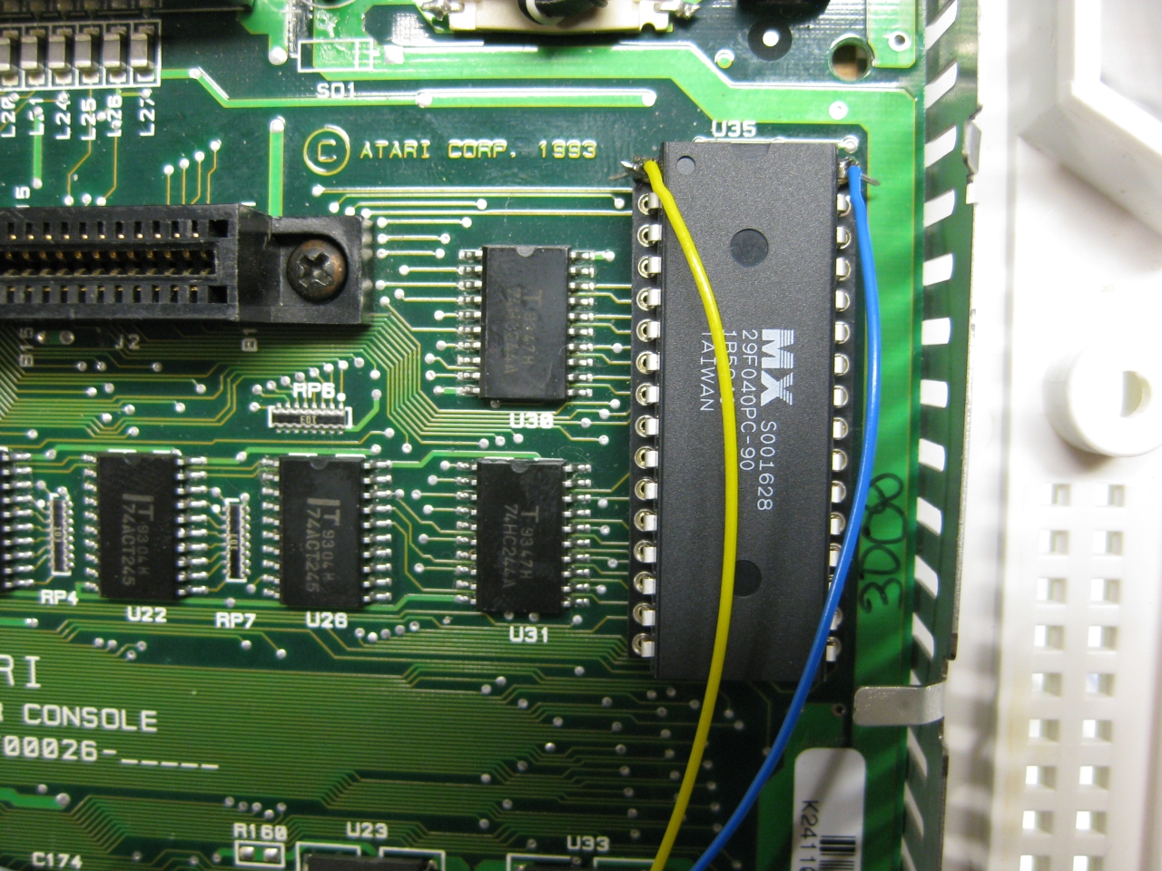
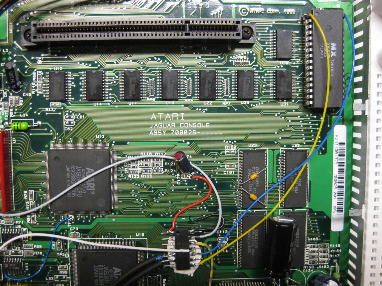
Its time to add a 2nd Bios to the Jaguar.
You have to remove the original Jaguar Bios and use a DIP 32 socket.
With the help of a 29f040 FlashRom I added jagbios and BJL1.06
You need to concat the bios files:
Use: windows command: copy /B jagbios.bin + jagbios.bin + jagbios.bin + BJL106.bin 4in1bios.bin
and burn 4in1bios.bin to the 29F040 FlashRom
(overview)
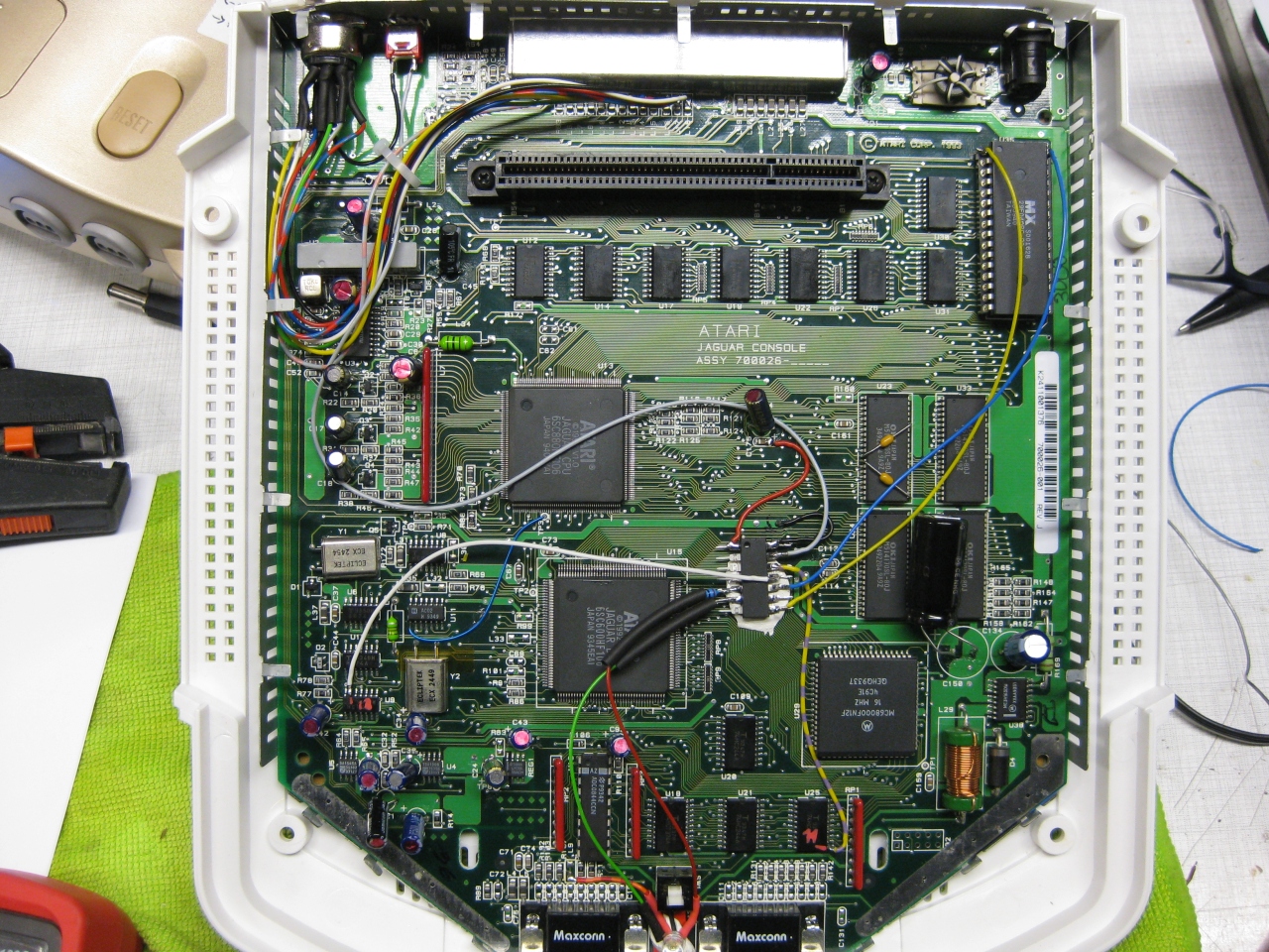
Update 23.6.2017
I put a switch beneath the Power Switch to make it like a „real switchless“ mod.
So the Power switch can pressed a litte to:
change 50/60
Reset
switch between original Bios and BJL
OR
Press it more deep to Power Off and Power ON like normal
I used a little switch with a ball at the end and put it inside like this:
 ,
,